AR1000 BULLETIN PAGE
Archive originally from the AOR-UK website in 2008, edited in 2022 by AOR Ltd. In Japan.
This information is supplied as a convenience to our loyal customers still using discontinued legacy AOR receivers.
Please note that the information is supplied “as is” without any support nor obligation. This model is no-longer accepted for repair and none of the parts are available anymore.
This information is supplied as a convenience to our loyal customers still using discontinued legacy AOR receivers.
Please note that the information is supplied “as is” without any support nor obligation. This model is no-longer accepted for repair and none of the parts are available anymore.
FairMate products
AOR and FairMate products were made on the same assembly line as 'OEM' branded items, their main PCBs and operation are the same but cosmetics are different. The operation of the FairMate HP100/200/2000 and AOR AR1000/2000 are the same.| Keypad |
| DC Socket |
| Microprocessor reset (to include H.F. coverage) |
| Unlocking Search & Scan banks |
| Frequency re-alignment |
| Keypad beep |
| Discriminator (detector) output |
TOP
AR1000 KEYPAD
A lot of these units are now quite a few years old and have experienced thousands of hours of use. One of items subject to wear is the keypad. Scan, search and manual buttons tend to wear first with operation becoming intermittent and eventually not responding at all. The keypad is an easy item to replace but requires the use of a soldering iron and a set of fine screwdrivers. Remove the battery cover and batteries. Remove the 4 screws holding the rear case and carefully lift this until the battery connection wire can be unplugged from the supply board. Unsolder the two earth wires from the RF board now visible. Unscrew the 3 board screws (threaded), pull the board rearwards and hinge it to one side. Remove the pillars holding the next board in place and de-solder the earth wire if fitted. Again this board can be hinged slightly to one side. The keypad is now situated under the CPU board. This can now be removed by unscrewing the 3 pillars and 1 screw (self-tapping), it may however be easier to remove the supply board as well from the bottom of the set. This requires the removal of 2 screws (self-tapping), 2 pillars and one earth wire. Note that the 2 small pillars on this are of a slightly different size to the 3 holding the CPU board. The keypad can now be easily replaced but it is probably a good idea to clean the PCB contacts before the new item is fitted. A brief wipe over with alcohol, IPA etc. should do. Rebuilding is obviously the reverse of the above but make sure that the correct pillars and screws are fitted in their various places. Take special care not to trap any wires.Whilst the keypad is no longer available, if your keypad's contacts are simply worn out (high resistance), it may be worth re-coating them with a specialist keypad repair kit. The original keypad contacts measured between 8k OHM and 16k OHM when new, when they had worn they read about 100k OHM (so you had to press hard to continue operation, by 500k OHM they fail). If the keypad is physically damaged (ripped etc.), the repair kit will not help and you will have to consider another approach.
TOP
AR1000 DC SOCKET
The power socket on these units gets a lot of wear and can eventually fail or become intermittent (intermittent supply levels are the main cause of crashed microprocessors in these sets). The socket itself can fail or the solder joints to the board can fracture. Either way, repair is simple, requiring removal of the rear case, 1 earth wire and lifting of the supply board. Replace or re-solder the socket but, as a further preventative measure, a wire can be soldered directly to the rear of the socket and taken to the anode of D201 (situated next to the socket).TOP
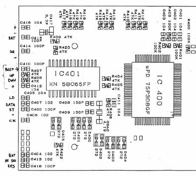
AR1000 Reset
The AR2001 can be reset in several ways:The AR1000 has no external RESET facility. In the case of a 'hang' or corruption, reset the microprocessor in the following manner. This will enable the coverage from 500kHz – 600MHz and 805MHz – 1300MHz (although performance drops off below 8MHz).
There are two methods, one involves connecting a diode between pin 13 and 51 on the microprocessor, this is tricky as track damage and short circuits are easy to create... we recommend the 'wire link' method shown below.

The best method is to add a wire link to the CPU board while the radio is switched off:
Switch the set on and PRESS the KEYS in the following order, the key presses should appear on the LCD as you enter detail... if it will not initiate, you may have to press BANK 1 several times until the number "1" appears:
BANK – 1 PROG – 0.5 – LIMIT – 49.995 – SEARCH – 561.225 – ENTER
2 – PROG – 50 – LIMIT – 107.995 – SEARCH – 561.225 – ENTER
3 – PROG – 108 – LIMIT – 169.995 – SEARCH – 561.225 – ENTER
4 – PROG – 170 – LIMIT – 296.995 – SEARCH – 561.225 – ENTER
5 – PROG – 297 – LIMIT – 600 – SEARCH – 251.575 – ENTER
6 – PROG – 805 – LIMIT – 1109995 – DOWN – 251.575 – ENTER
7 – PROG – 1110 – LIMIT – 1300 – DOWN – 561.225 – ENTER
Note: If line five is altered as shown here, coverage without a gap will be achieved (but reception between the 600 - 805 MHz range is not guaranteed).
5 – PROG – 297 – LIMIT – 804.995 – SEARCH – 251.575 – ENTER
Switch off the set and disconnect the diode/wire. The microprocessor will now be reset and all memory banks empty. It is recommended that at least one frequency be keyed into each memory bank. Now reprogram each of the 10 search banks.
i.e. SEARCH PROG (start frequency) LIMIT (stop frequency) ENTER (search step in kHz) ENTER (mode) ENTER (bank number) ENTER SEARCH
SEARCH – PROG – 118 – LIMIT – 138 – ENTER – 25 – ENTER – AM – ENTER – 1 - SEARCH
SEARCH – PROG – 225 – LIMIT – 399.9 – ENTER – 50 – ENTER – AM – ENTER – 2 – ENTER – SEARCH
SEARCH – PROG – 71 – LIMIT – 87 – ENTER – 12.5 – ENTER – AM – ENTER – 3 – ENTER – SEARCH
SEARCH – PROG – 165 – LIMIT – 174 – ENTER – 12.5 – ENTER – FM – ENTER – 4 – ENTER – SEARCH
SEARCH – PROG – 174.5 – LIMIT – 225 – ENTER – 12.5 – ENTER – FM – ENTER – 5 – ENTER – SEARCH
SEARCH – PROG – 156 – LIMIT – 163 – ENTER – 25 – ENTER – FM – ENTER – 6 – ENTER – SEARCH
SEARCH – PROG – 144 – LIMIT – 146 – ENTER – 12.5 – ENTER – FM – ENTER – 7 – ENTER – SEARCH
SEARCH – PROG – 433 – LIMIT – 435 – ENTER – 25 – ENTER – FM – ENTER – 8 – ENTER – SEARCH
SEARCH – PROG – 890 – LIMIT – 905 – ENTER – 12.5 – ENTER – FM – ENTER – 9 – ENTER – SEARCH
SEARCH – PROG – 935 – LIMIT – LIMIT – 950 – ENTER – 12.5 – ENTER – FM – ENTER – 0 – SEARCH
The reset and reprogramming is now complete.
TOP
AR1000 Unlocking Search and Scan Banks
In cases where the set does not appear to operate correctly, first try these few ideas... it usually is simply "finger" trouble.SCAN
1) Memory banks which contain no data will not be scanned, this sometimes happens when channels have been deleted by the customer (or following a microprocessor reset). Enter data into at least one channel of each bank and try scan again.
i.e. MANUAL 1 3 3 . 7 ENTER
PROG 000 PROG 100 PROG 200 PROG 300 etc.
2) Ensure that ALL banks are listed for scan. To reinstate all memory banks SCAN BANK PROG 0 LIMIT 9 ENTER
SEARCH
1) Ensure that all banks are listed for search. To reinstate all search banks SEARCH BANK PROG 0 LIMIT 9 ENTER
(On the AR1500 SEARCH BANK PROG 0 LIMIT 8 ENTER as bank 9 is reserved for automatic memory store).
2) Ensure that data is correctly stored in the search parameters
SEARCH PROG 150 LIMIT 160 ENTER 25 ENTER FM ENTER "X" ENTER SEARCH
Where "X" is the bank which you wish to reprogram (i.e. 1,2,3, etc.).
3) Check that the first frequency of a search bank is not locked out, this is how the receiver of a search bank is not locked out, this is how the receiver decides whether the search bank is locked out.
SEARCH BANK PROG LOCKOUT
The first locked out frequency will appear on the display, to release it press LOCKOUT or to move on to the next press ENTER
Hunt for the first frequency of each search bank to ensure that they are not locked out release them by pressing LOCKOUT
Alternatively simply unlock every frequency in the lockout list - but this may take some time as there could be as many as 1000.
When the last frequency is unlocked the receiver will start searching. Don't go too quickly or you may start LOCKING OUT new frequencies rather that UNLOCKING old ones... this may be the case if all the frequencies suddenly appear numeric!! If so just start point 3 again.
TOP
AR1000 FREQUENCY ALIGNMENT
The AR1000 does have a tendency to drift in frequency with age. Later sets do not suffer to the same degree (different xtal manufacturer used) and quite often an older set once re-aligned will stay reasonably stable. The main culprit for the drift is the 154.825MHz oscillator but if the main PLL ref 'osc' is not bang on 12.8MHz, aligning just the 154.825 osc' will cause misalignment in other ranges. At full operating temperature, align the 12,8MHz xtal with CV1 and CV2 (coarse and fine). Both are located on the top (RF) board at the bottom edge. CV2 is located on the solder side of the board next to PLL chip TC9181F and CV1 on the component side next to the 12.8MHz xtal. Both of these trimmers are usually near the end of their range.The 12.8MHz frequency will have to be measured with an accurate frequency counter either sniffed directly from the xtal can or at the input to the PLL IC on pins 2 & 3. If using the latter method, take care not to shift the frequency by loading these points.
The radio can now be aligned by ear with a suitable signal (for ex. for NFM on marine band or 2 meters ham band). With a suitable signal being listened to, align the 154.825MHz oscillator for best reception. The easiest way to check for correct alignment is by listening to a low-level signal and tuning 5KHz either side of it to check if the alignment really is centered on the wanted frequency. The 154.825MHz xtal can be aligned at CV3 (located on the solder side of the RF board opposite the 154.825 xtal). This will give a small adjustment but it is generally better to align transformer T10 located next to the xtal (green core fitted). In both cases, check that the xtal is not operating on the edge of its range and that it starts up on switch on every time (i.e. reception is obtained immediately on switch on). After alignment, check that the set is on frequency throughout its frequency range.
TOP
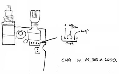
AR1000 Keypad Beep
The keypad "BEEP" was present on early units but has been disabled later on. However by addition of a single wire, the facility can be restored.Switch the receiver off and remove the batteries. Disconnect the receiver from the AC charger and remove the rear case. 4 screws secure the rear case half (2 x in rear case - 2 x in battery box). You will see 3 PCB layers once inside the case.
One end of the wire connects to the outer edge of CN9 on the top PCB. This is located at the base of the rotary tuning control. The original wire is usually GREY and the "tail" can sometimes be seen. If this is the case, solder a new length of wire to the tail. If no tail is visible, solder a new length of wire to the corresponding point on the PCB. Use the foil side (facing upward) of the PCB, this will save you "taking the set to bits"!
The other end of the wire connects to the bottom PCB (which carries the microprocessor). Follow the 3 existing wires from CN9 to the bottom board. With the base of the set facing you an unused "LAND" will be visible on the PCB to the left of the 3 existing wires. If you are lucky a tail will be connected.
If you are very careful and use a small soldering iron then there is no need to separate the PCB's. Solder the free end of the new wire to the "LAND or Tail".
Re-assemble the case and test. You will now have a KEYPAD BEEP.
Note: If you find it necessary to separate the PCB's, then the earth bonding wires will need de-soldering from the edge of each PCB. Make sure you reconnect them when you re-assemble the receiver.
TOP
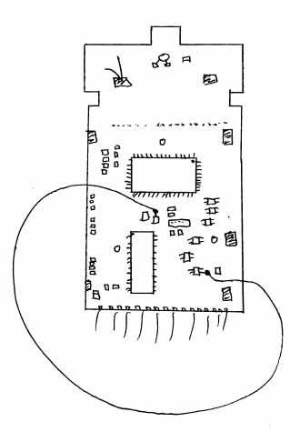
AR1000 Discriminator (detector) output
Remove the rear cover (4 screws) taking care not to damage the battery wires while pulling the case apart. The battery wires will unplug from the power supply board if required.The rear of the main PCB is now visible.
The discriminator output can be taken from IC5 pin9.
On the AR1000, this is fitted to the reverse side of the board (the solder side that is now visible).
IC5 is located about 2/3 of the way down the board (starting from the top) and about 1/2 way across.
It is labelled TA7761P although this may be difficult to read due to lacquer on the device.
Simply solder a wire to pin 9 of this IC to obtain the discriminator output.
Terminate the wire at a suitable socket and re-fit the case half (you may find that removing the side-panel case stopper provides an excellent location without the need to drill or burn a hole in the cabinet).
TOP
Please note that the information is supplied “as is” without any support nor obligation. This model is no-longer accepted for repair and none of the parts are available anymore.
www.aorja.com