AR1500 BULLETIN PAGE
Archive originally from the AOR-UK website in 2008, edited in 2022 by AOR Ltd. In Japan.
This information is supplied as a convenience to our loyal customers still using discontinued legacy AOR receivers.
Please note that the information is supplied “as is” without any support nor obligation. This model is no-longer accepted for repair and none of the parts are available anymore.
This information is supplied as a convenience to our loyal customers still using discontinued legacy AOR receivers.
Please note that the information is supplied “as is” without any support nor obligation. This model is no-longer accepted for repair and none of the parts are available anymore.
| IC7 (TA78L009AP) input regulator replacement |
| Microprocessor reset |
| Unlocking Search & scan banks |
| Discriminator output |
| LCD segments |
TOP
AR1500 IC7 (TA78L009AP) input regulator replacement
If any problem is experienced with the supply or battery circuit with an AR1500 or AR1500E, the chances are that IC7 has failed (78L009). This can occur due to a fault within the charge circuit, reverse polarizing the socket or under certain circumstances IC7 can receive a brief reverse current causing failure. IC7 is located close to the power socket and can be easily replaced. It is a 9V regulator but the correct device needs to be used (a 78L09 will not work correctly).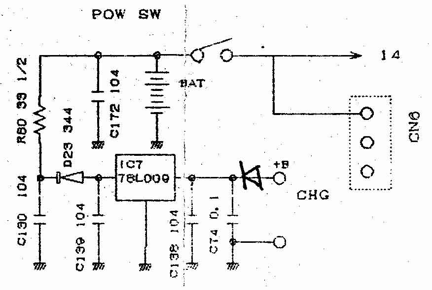
To prevent any further problems, fit a diode in line with the input to IC7 (between the charge socket and input leg). A PCB track will have to be broken to do this. Any diode capable of passing over 200mA current will do. Most later sets will already have this fitted (visible on solder side of PCB next to power socket connections). All AR1500EX models have it fitted as standard - IC7 is re-labelled IC4 in the EX model.
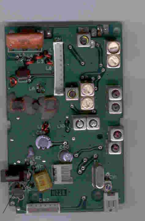
The left picture above is of the AR1500 RF PCB (this is what you will see when you remove the rear cabinet of the radio). Near to the DC input socket (bottom right corner) you will see an added input protection diode 1N4007, one end of the diode feeds the INPUT of the regulator. The regulator has three in0line pins, 12V input feed is to the inner pin, the center pin is ground and the pin closest to the edge of the PCB is 9V out. A small black line has been used on the picture to draw attention to the diode.
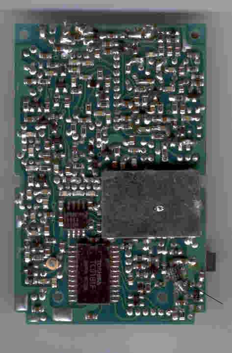
The right picture is the opposite side of the same PCB. A black line is used to point to the regulator in the bottom left corner of the PCB. When replacing the regulator, simply match the shape of the plastic package to the outline printing of the PCB (flat side of the package faces toward the bottom edge of the PCB.
TOP
AR1500 Microprocessor reset
The information stored in the memory channels (scan banks) and search bank is permanently held in an EEPROM (Electrically Erasable Programmable Read Only Memory). No battery backup is required.In the extremely unlikely event you should encounter problems with memory loss or corruption it may be possible for you to RESET the microprocessor. This scenario may occur due to static discharge from mobile operation, connection to an external aerial, shipping in plastic & polystyrene materials or from noise on the power feed to the receiver.
A small RESET slide switch is located in the battery compartment of most (BUT NOT ALL) AR1500 receivers. This switch is covered by a protective tape and is connect to a short length of wire.
If a reset switch is not present, you will require further technical information!
1. Switch the AR1500 off and remove the battery cover and NiCad pack.
2. Remove the protective tape from the slide switch.
3. The switch has two positions, carefully slide the switch from the first to the second position.
4. Insert the NiCad pack and switch on the receiver.
5. The display should be blank at this time.
6. Carry out the following key strokes very carefully, take your time. If you make a mistake switch the receiver Off/On and start again. If the first sequence of [BANK] [PROG] has no effect repeat these key presses as required. The key strokes should appear on the LCD as you progress.
7. Execute exactly as shown! (ignore the " - "separator):
When you switch the set on, PRESS the KEYS in the following order, the key presses should appear on the LCD as you enter detail... if it will not initiate, you may have to press BANK 1 several times until the number "1" appears:
AR1500 & AR1500E
BANK - 1 - PROG - 0.5 - LIMIT - 1.995 - SEARCH - 556.325 - ENTER
2 - PROG - 2 - LIMIT - 299.995 - SEARCH - 556.325 - ENTER
3 - PROG - 300 - LIMIT - 419.995 - SEARCH - 249.125 - ENTER
4 - PROG - 420 - LIMIT - 606.995 - SEARCH - 249.125 - ENTER
5 - PROG - 607 - LIMIT - 797.995 - SEARCH - 58.075 - ENTER
6 - PROG - 798 - LIMIT - 1105995 - [DOWN KEY] - 249.125 - ENTER
7 - PROG - 1106 - LIMIT - 1300 - [DOWN KEY] - 556.325 - ENTER
AR1500EX (it's slightly shorter)
BANK - 1 - PROG - 0.5 - LIMIT - 95.995 - SEARCH - 556.325 - ENTER
2 - PROG - 96 - LIMIT - 299.995 - SEARCH - 556.325 - ENTER
3 - PROG - 300 - LIMIT - 512.995 - SEARCH - 249.125 - ENTER
4 - PROG - 513 - LIMIT - 797.995 - SEARCH - 58.075 - ENTER
5 - PROG - 798 - LIMIT - 1105995 - [DOWN KEY] - 249.125 - ENTER
6 - PROG - 1106 - LIMIT - 1300 - [DOWN KEY] - 556.325 - ENTER
8. Switch off the receiver and remove the NiCad pack.
9. Carefully slide the switch into its original position and replace the protective tape.
10. Insert the NiCad pack once again and switch on.
11. Test the receiver fully.
Notes: This procedure resets the microprocessor and clears the contents from the memory channels - they will now be blank! The search banks may differ from the defaults shown in this manual, in this case you will need to reprogram them.
You have instructed the operating system of the AR1500 to receive selected bands with selected Intermediate Frequencies (IF), if your keystrokes faithfully followed the above then you will have an unbroken coverage from 500 kHz to 1300 MHz without gaps. If you receiver a <Fr.Err> message, you have probably made a mistake - try again.
Note: To ensure the best microprocessor stability, never delete ALL memory channels from a scan bank, it is a good idea to leave at least one active channel in each bank... i.e. 000, 100, 200 etc. Do not limit the scan range to a memory bank which is totally empty.
TOP
AR1500 Unlocking Search and Scan Banks
In cases where the set does not appear to operate correctly, first try these few ideas... it usually is simply "finger" trouble.SCAN
1) Memory banks which contain no data will not be scanned, this sometimes happens when channels have been deleted by the customer (or following a microprocessor reset). Enter data into at least one channel of each bank and try scan again.
i.e. MANUAL 1 3 3 . 7 ENTER
PROG 000 PROG 100 PROG 200 PROG 300etc
2) Ensure that ALL banks are listed for scan. To reinstate all memory banks SCAN BANK PROG 0 LIMIT 9 ENTER
SEARCH
1) Ensure that all banks are listed for search. To reinstate all search banks SEARCH BANK PROG 0 LIMIT 8 ENTER
(On the AR1500 SEARCH BANK PROG 0 LIMIT 8 ENTER is employed as bank 9 is reserved for automatic memory store).
2) Ensure that data is correctly stored in the search parameters
SEARCH PROG 150 LIMIT 160 ENTER 25 ENTER FM ENTER "X" ENTER SEARCH
Where "X" is the bank which you wish to reprogram (i.e. 1,2,3, etc.).
3) Check that the first frequency of a search bank is not locked out, this is how the receiver of a search bank is not locked out, this is how the receiver decides whether the search bank is locked out.
SEARCH BANK PROG LOCKOUT
The first locked out frequency will appear on the display, to release it press LOCKOUT or to move on to the next press ENTER
Hunt for the first frequency of each search bank to ensure that they are not locked out release them by pressing LOCKOUT
Alternatively simply unlock every frequency in the lockout list - but this may take some time as there could be as many as 1000.
When the last frequency is unlocked the receiver will start searching. Don't go too quickly or you may start LOCKING OUT new frequencies rather that UNLOCKING old ones... this may be the case if all the frequencies suddenly appear numeric!! If so just start point 3 again.
TOP
AR1500 discriminator output
There is no standard discriminator output on the AR1500 /E/EX models. However it is possible to obtain discriminator (detector) output by wiring directly to the NFM discriminator chip, this is IC 3 MC3372 pin 9 located on the I.F PCB (the larger SMD chip on the underside of the board, pin 1 is marked with a dot/circle - count pin numbers anti-clockwise).A suitable ground may be taken from almost and point close to whatever socket you mount on the unit to provide a durable connection or use pin 15 on IC3 MC3372.
Depending upon the loading of your external circuit, you may need to buffer the connection to the discriminator with a capacitor, resistor or both (otherwise it may result in little or no audio output from the receiver).
TOP
AR1500 LCD segments
On a few occasions, the LCD of the AR1500 produces faint segments... this may vary with ambient temperature and physical pressure being exerted on the receiver's cabinet. Before considering replacement of the LCD, try heating each of the metal contacts which connect from the PCB to LCD with a tip of a small soldering iron while exerting downward pressure on the LCD through the soldering iron. The contact will press into the LCD plastic-type material and will quickly key the contact into place... obviously do not overdo the heat or pressure! There is a large row of contacts on the bottom side of the LCD with a smaller row on the top side, just heat them all and assess the results.TOP
Please note that the information is supplied “as is” without any support nor obligation. This model is no-longer accepted for repair and none of the parts are available anymore.
www.aorja.com