AR3000A BULLETIN PAGE (not for AR3000)
Archive originally from the AOR-UK website in 2008, edited in 2021 by AOR Ltd. In Japan.
This information is supplied as a convenience to our loyal customers still using discontinued legacy AOR receivers.
Please note that the information is supplied “as is” without any support nor obligation. This model is no-longer accepted for repair and none of the parts are available anymore.
Some pdf files linked in this archive might mention contact details for AOR-UK Ltd. These are not valid anymore and can be ignored.
AR3000A RESET
Remove both top and bottom covers, the reset switch is located on the rear of the front CPU board. The required switch is the small momentary push switch located in the corner of the PCB (behind the X10 button - not the slide switch which sets RS232 baud rate). With the set connected to power and the on/off switch on, push this switch, hold for one second then release. The reset will take a short while and all LCD characters will appear for a few seconds. When the reset is complete, the AR3000A reverts to its normal operating mode (clock set back to zero, memories back to factory defaults etc.).TOP
AR3000A BACK UP BATTERY REPLACEMENT
When battery voltage drops below 2.80V (using a DVM) it is time to replace the battery Its nominal voltage is 3.0V. The battery is a solder type CR2032.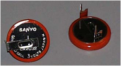
The memory back up battery can be replaced quite easily with the use of screwdrivers and a soldering iron. This involves removal of the top and bottom case halves (6 screws) and the front panel (4 screws). With the CPU board exposed, the battery can be located behind it on the right-hand side. This is best de-soldered from the front of the board in between the keyboard switches. Care must be taken not to short the new battery when fitting it and check that the polarity is correct (+ & - are marked on the board). Carry out a micro reset once the new battery has been fitted as it is possible for the unit to be in a crashed state and a higher-than-normal amount of current may be drawn, shortening battery life.
If you are left looking at a small black plastic gate, it has fallen out from the space between the front panel of the radio and microprocessor PCB. Look carefully at the gate, you will notice that there is a cut-out. This is to enable the gate to fit roughly in the middle of the microprocessor PCB with the cut-out facing the PCB so that it sits flat against the board, avoiding the raised solder contacts. The gate appears to be a mechanical protection device to prevent the front panel from smashing into the microprocessor PCB if a very heavy blow is encountered. Occasionally the gate causes poor mechanical operation of the keys. If so, slacken the four screws which hold the front panel in position, maneuver the panel and re-tighten the screws so that the keys operate smoothly. If you cannot achieve positive action of the keys (or can't work out where to place the gate), throw the gate away. Occasionally the gate is omitted during manufacture. The microprocessor PCB has five holes for the screws to secure it to the metal chassis, however there are usually only four screws fitted (don't look for the missing screw under your chair, it's not there).
TOP
AR3000A PRE-AMP
A pre-amp is fitted for use over the shortwave range (100kHz to 30MHz). This is normally switched on. If additional attenuation is required or mixing problems experienced (using large antennas?) then turn the pre-amp off. The switches for this are located under the top cover (both covers will have to be removed) on the front, left hand side. The switches have to be either both ON or both OFF for receive to be possible. If your set appears very deaf below 30MHz, check the position of these switches. - It wouldn't be the first time we have seen a set returned with a reported "no SW RX" due to one switch being ON and the other OFF.TOP
AR3000A AGC & RSSI
In response to your queries regarding s-meter /AGC output from the AGC, our measurements are as follows:Computer control signal reporting "letter" against dBm signal level provides the following results.
Frequency of test is 130.200MHz AM with 70 percent modulation and 1kHz tone:
| dBm range | RS232 letter |
|---|---|
| -110 to -108 | A |
| -107 to -105 | B |
| -104 to -102 | C |
| -101 to -99 | D |
| -98 to -96 | E |
| -95 to -92 | F |
| -91 to -88 | G |
| -87 to -83 | H |
| -82 to -76 | I |
| -75 to -63 | J |
| -62 to -40 | K |
| -39 to -38 | L |
AGC levels taken directly from AGC line (suitable point, Pin-10 of J9 IF PCB).
Frequency of test is 130.000MHz AM with 70 percent modulation and 1kHz tone:
| Input signal (uV) | AGC voltage |
|---|---|
| 0 | 4.83 |
| 1 | 4.01 |
| 3 | 3.20 |
| 5 | 2.90 |
| 10 | 2.60 |
| 14 | 2.48 |
| 16 | 2.46 |
| 20 | 2.37 |
| 50 | 2.12 |
| 100 | 1.97 |
TOP
AR3000A INTERMITTENT OR OPEN SQUELCH
If the receiver squelch becomes intermittently OPEN regardless of squelch control position and changes with mechanical movement of temperature, the unit may be suffering from a cracked surface mount component on the i.f. PCB.Have a look at the solder side of the PCB (the i.f. PCB is the bottom board), you will need to temporarily remove it from the radio.
Look on the opposite side of the board to the ceramic resonator marked CF2 (usually orange in color). There are usually two added conventional components, one being a resistor (12k) and the other a disk ceramic capacitor (possibly green in color) with a value of 102 (1000pF).
The capacitor is attached to a 3-pin device at one end and is soldered between a SMD resistor and SMD capacitor at the other... the capacitor may be cracked ??
Temporarily lift one leg of the disk capacitor and see if the SMD capacitor falls in two!
Replace the SMD cap (size is 0805), the value is 103 (C170). In 'real language' this is 0.01uF or may be expressed as 10nF.
On one occasion, it has been reported that another SMD capacitor C82 (103 / 0.01uF / 10nF) was also faulty resulting in confusing squelch problems, this capacitor is situated just one component away from C170, only R190 separates the two components.
Re-build and test.
A picture of the underside of the IF PCB with close-up of the components is available as a pdf - click here..
TOP
AR3000A 5V SMD regulator replacement
The surface mount 5V regulator IC10 (S-81250HG), runs constantly if power is connected to the unit. It provides the main supply to the microprocessor board and also the backup supply when the power is still connected but the unit not switched on. This prolongs the lithium back up battery life.The regulator should be able to run constantly for the entire life of the set without problems if required. Occasionally one may fail and require replacing. This is however very unusual and is most probably due to a 'push' from some other source. e.g. having to dissipate the extra heat from using a higher-than-normal voltage power source or some other failure within the set drawing extra current from the 5V line.
If the device fails, the symptoms are that the unit will not power up and the clock is not displayed at all. Don't get this confused with a crashed microprocessor, as symptoms can be very similar. A re-set, however, will not cure the regulator fault. A failed internal fuse will also give similar symptoms.
To carry out the work:
Remove bottom case half (4 screws), this exposes the main IF board.Check if the regulator has failed by connecting power (power switch on or off) and measuring for 5V at pin 1, connector J9. These are located on the multi-pin connector close to the remote socket and are clearly labelled. For information, viewed from the top of the SMD device (IC10) with three legs to the left, the designations from top to bottom are G, V-in, V-out). Remove the power again.
Looking from front of set:
Remove two mini coax connectors (J3 & J10) from the left-hand side of the board. Note that these are quite easily damaged and it is best to remove them with a straight upwards pull with a pair of pointed pliers (don't lever them sideways as the center connection will be damaged).
Remove the three 2-pin coax connectors (J4, J5 & J11).
Remove the board screws (6 in all).
This allows the board to hinge towards the rear of the set without removing any further connectors.
Again, looking from the front of the set, IC10 is located on the solder side of the board near the left-hand edge. It is positioned between the screw head (holding regulator IC11) and the side of the board.
Remove the solder from the three legs on one side of the regulator.
Hold the soldering iron on the single leg at the other side and lift the device clear of the board with a pair of fine pliers.
If the device does not lift, do not force it as the tracks may pull away. Try de-soldering the legs again.
Clean the solder pads and fit the new device.
Reassemble the unit in the reverse order to the above.
Take care not to trap any wires when re-fitting the PCB. Take particular care if the unit is a plus set as several more wires pass down the right-hand side of the set.
Note: When re-fitting the connectors, they usually fall back into the correct place. If they don't;
J10 is the long wire coming from the center VCO board.
J1 is the shorter wire coming from the top RF board.
J11 is marked red.
J4 is marked white.
J5 is the unmarked grey wire.
Before fitting the case, connect power to the set and check that 5v is present on pin 1 of J9. Now refit the cover and test the set.
TOP
AR3000A PLL ERROR display
If a fault occurs within the PLL system of the AR3000A, the microprocessor has been programmed to display a PLL UNLOCK message 'PLL ERR' on the LCD.1. If a CPU corruption occurs, it is possible to encounter a PLL ERROR, first try to reset the CPU to restore normal operation. This is particularly valid if the backup battery has become exhausted
2. We have noted occasional PLL unlock in the 900MHz frequency range due to a VCV supply SMD electrolytic capacitors drying out.
| Faulty capacitors C31 (1uF/35V) or C32 (4.7uF/35V). Both are on VCV line. |
| Faulty capacitors C24 & 25 (2.2uF/20V) - back-to-back caps in VCV circuit. These may be faulty even though they don't measure leaky. |
There are no really common failures but if none of above appear at fault, check supply lines at:
| Connector J1. Pin 1 is 5V, pin 2 is 9V |
| Check voltage is multiplied through IC5 (TL499) |
| Check for 6.2V on output from IC6 |
| Check for 12.8MHz oscillator output |
After that, it's a case of working through the loop:
IC1, IC2, IC4, module NIS130 etc.
TOP
Microprocessor instability on very early units
The AR3000A appeared in relatively small quantities at the end of 1991. A small percentage of production units (up until March 1992) suffered from microprocessor instability (crash). This was addressed by the addition of a few resistors to the CPU PCB. A bulletin pdf was generated in March 1992 - click here.TOP
AR3000A PC leads & wiring
If you wish to make up your own lead:| AR3000A 25-way male plug required | PC 25-way female plug required |
|---|---|
| 1 | 1 SCREENED CABLE only to PC end |
| 2 | 2 |
| 3 | 3 |
| 4 | 4 |
| 5 | 5 |
| 7 | 7 SIGNAL GROUND |
| AR3000A 25-way male plug required | PC 9-way female plug required |
|---|---|
| 1 | 1 SCREENED CABLE only to PC end |
| 2 | 3 |
| 3 | 2 |
| 4 | 7 |
| 5 | 8 |
| 7 | 5 SIGNAL GROUND, also attach the SCREENED CABLE only to PC end |
TOP
AR3000A audio output level
The operating manual quotes for speaker output level as follows:- 1.2W into 4ohm
- 0.7W into 8ohm
However 1.1W into 8ohm is closer to reality.
The AUX socket audio level is not specified in the manual; however measurements are given here:
Using a 1k OHM load (for want of a better value), pin 2 is ground.
- Output from pin 4 is 1.2v peak to peak.
- Output from pin 5 is 5mV p/p.
Note: The audio output at pin 4 is simply a tap straight from audio output stage of the receiver before the volume control and audio IC. It is capacitively coupled back to the previous stage but is DC coupled straight across the 50k OHM volume potentiometer. The low-level output is the same output but with a 220K ohm resistor in series - the output into a very high impedance load with therefore be much greater than 5mV.
TOP
Please note that the information is supplied “as is” without any support nor obligation. This model is no-longer accepted for repair and none of the parts are available anymore.
www.aorja.com