AR7030 BULLETIN PAGE
Archive originally from the AOR-UK website in 2008, edited in 2021 by AOR Ltd. In Japan.
This information is supplied as a convenience to our loyal customers still using discontinued legacy AOR receivers.
Please note that the information is supplied “as is” without any support nor obligation. This model is no-longer accepted for repair and none of the parts are available anymore.
Some pdf files linked in this archive might mention contact details for AOR-UK and AOR Manufacturing Ltd. These are not valid anymore and can be ignored.
AR7030 filter calibration
The following describes the operation of the filter calibration routines in the AR7030 which will explain the figures observed. The Filter calibration system in the AR7030 serves three main purposes :1) to calibrate the filter center frequency offsets required for LSB and USB operation so that the filters give consistent carrier attenuation and tonal quality despite widely varying characteristics.
2) to enable additional or changed filters to be incorporated easily, set up for optimum operation and identified and selected by the radio operator.
3) to select the appropriate IF tail filter to match the bandwidth of each user selected filter.
The system operates by feeding a variable frequency IF signal through each filter in turn and monitoring the filter attenuation using the receiver's AGC system. The filter is scanned below and above its nominal center frequency and the points where the signal is reduced by 8dB and 20dB are recorded.
The -8dB point is used, rather than -6dB, because the filter's transition slope is steeper at this point and with the rather granular measurement of the AGC system this provides a more consistent assessment of the filter's bandwidth. The receiver software then applies a correction to the measured -8dB bandwidth to produce a typical -6db figure and to allow for the effects of the IF tail filter, which is outside the AGC measurement loop (see the AR7030 block diagram).
The corrected -6dB bandwidth is used to select the most appropriate IF tail filter bandwidth (4kHz or 10kHz) and to provide the entry in the filter bandwidth table for user identification. The Filter table order is set by sorting these bandwidth figures into ascending order. Note that the calibration routine tests the filters in the order in which they are installed in the circuit board, and the filter numbers displayed are not necessarily the same as the numbers shown when filters are selected in the FILTER menu.
The -20dB filter frequencies are used to establish the USB and LSB carrier positions for each filter. The filter offsets are internally limited to +/- 3kHz because there is little need to apply a full USB or LSB offset to the widest filters, but filters up to 4kHz bandwidth will be set to eliminate the unwanted sideband, with a carrier attenuation of 20dB.
An average frequency between the -20dB points is used as the filter center frequency for CW, DATA, AM and Sync modes. The PBS offset display is based on this calculated center frequency rather than the nominal 455kHz center of the filters. This allows for manufacturing tolerances and thermal variations.
Because the calibration system shares many common parts with the PBS system its frequency range is similarly limited to +/- 4.2kHz. In practice this is not a problem because very accurate calibration is only needed for the narrower filters used in SS B modes, and the wider filters, used mainly for AM and NFM, will tolerate a few hundred Hertz center offset without any noticeable effect.
Because of these frequency limitations the maximum -8dB bandwidth that can be measured is 8.5kHz, which will report as a -6dB bandwidth of 6.7kHz. Any filters that are wider than this will all report the same bandwidth. The standard 9.5kHz filter is a special case (which is why it cannot be changed) and it will always have a bandwidth of 9.5kHz entered in the filter table.
TOP
AGC output - analogue S-meter
Several people have expressed a desire to add an external analogue signal meter to the AR7030 receiver. The easiest way is to tap into the AGC line and take a single wire to an unused pin on the rear panel AUX socket of the AR7030. An PDF technical bulletin on this subject has been generated (34kb) - click here.The AGC output is taken directly from the AGC amp so any loading will pull it very slightly. The signal is then fed through a 100k resistor to the input of another op-amp paralleled be a 150k resistor to ground. So keep the load resistance as high as possible but there should be no noticeable difference if you load it with 470k (just drop a fixed resistor from the AGC line to ground and see if it pulls the s meter reading).
In June 2002, the AR7030 re-mailer discussed external s-meter and Guy Atkins posted a PDF file initially generated for the JRC NRD525 commenting that it may be adaptable for the AR7030. The file is available here, we offer no warranty or support for the data nor do we hold and copyright or claim to the material (429kb) - click here.
TOP
S-meter calibration viewed from the front panel
The following table gives an idea of s-meter reading against input signal fed to the 50 OHM aerial socket of the AR7030.The input is relatively flat across the frequency range of the receiver. As careful attention is given to the AGC calibration during manufacture of each radio, results will be very close from set-to-set, maybe within 3dB or so.
This table was generated using a current production AR7030 at 7.1MHz AM with an unmodulated signal feeding the 50 OHM aerial socket with WHIP AMP OFF and PREAMP OFF. The test was carried out using FILTER-3, this is the first filter down from the 9.5kHz filter
| S1 | -113dBm | 0.50uV |
| S3 | -103dBm | 1.58uV |
| S5 | -93dBm | 5.0uV |
| S7 | -83dBm | 15.8uV |
| S9 | -73dBm | 50.0uV |
| S9+10 | -63dBm | 158uV |
| S9+20 | -43dBm | 1.58mV |
| S9+50 | -23dBm | 15.8mV |
TOP
AR7030 IMPROVEMENT OF INTERMODULATION PERFORMANCE
Under extreme reception conditions we have had a report of some intermodulation in the area around 1.8MHz. It has been found that there is a slight tailing off of IP3 performance in the lower frequency ranges. This is due to the type of components used in the 1.7MHz HPF/LPF area of the set.A modification to give flat performance from 500KHz to 30MHz can be easily carried out. This involves replacement of several surface mount components with conventional types.
To carry out this; Remove the top and bottom case halves (4 & 6 screws respectively).
Remove the right-hand side rail (5 screws). For ease of access, it is also a good idea to remove RL3 taking care not to damage any solder pads.
Remove surface mount components C22 to 27 and L8 to 11.
These should be replaced with Philips 630 series, 100v Med-K ceramic plate capacitors and Siemens B78108-T series axial leaded inductors.
Values are as follows;
C22 1n8(10%)
C23 1n0
C24 1n8
C25 2n2
C26 3n9
C27 2n2
L8 3.3uH (10%)
L9 3.3u
L10 6.8u
L11 6.8u
Crop the leads as short as possible and solder them to the now vacant pads. The inductors can be mounted vertically.
Refit RL3 and the case parts. The top case should be fitted before the bottom one and the screws only tightened very slightly in order to avoid stripping the threads.
Note that most sets have already be fitted with better specification components.
TOP
RS232 signal meter reading - additional comments
Several commercial organizations are using the AR7030 for signal monitoring purposes and wish to accurately log signal meter level. The information is given in the RS232 PROTOCOL LISTING but the subject is fairly complex. A summary of the required process is given here, the text has been generated by John Thorpe in response to a commercial request for more detailed guidance (November 2001).Reading the input signal strength from the AR7030 is not too difficult, but some math is needed to convert the level into dBm.
Each set is calibrated after manufacture and a set of S-meter calibration values stored in EEPROM in the receiver. This means that the signal strength readings should be quite good and consistent. I think that you should get less than 2dB change with frequency and maybe 3dB with temperature. Initial calibration error should be less than +/- 2dB.I think the sets that you use have been modified for DRM use have some changes in the IF stage. This will require that the sets are re-calibrated if you are to get accurate results. The SM7030 service kit has a calibration program (for PC).
The signal strength is read from the AGC voltage within the 7030 so AGC should be switched on and RF Gain set to maximum. To read AGC voltage send opcode 02EH (execute routine 14) and the receiver will return a single byte value between 0 and 255 which is the measured AGC voltage.
The calibration table is stored in EEPROM, so the control software should read this when connection to the receiver is established and store the data in an array for computing.
Calibration data is 8 bytes long and is stored in Page2 at locations 500 (01F4H) to 507 (01FBH). Use the PaGE opcode (052H) then SRH, ADR, ADH to setup the address, then 8 RDD opcodes to read the data, as below :-
Opcode Hex Operation
PGE 2 052H Set page 2
SRH 15 03FH H register = 15
ADR 4 044H Set address 00F4H
ADH 1 011H Set address 01F4H
RDD +1 071H Read byte 1 of cal data
RDD +1 071H Read byte 2 of cal data
. . . . . . . . . . . . . . . . . . .
RDD +1 071H Read byte 8 of cal data
PGE 0 050H Return to page 0 for subsequent control operations
The first byte of calibration data holds the value of the AGC voltage for a signal level of -113dBm (S1). Successive bytes hold the incremental values for 10dB increases in signal level :-
Cal data Typical Value RF signal level
byte 1 64 -113dBm
byte 2 10 -103dBm
byte 3 10 -93dBm
byte 4 12 -83dBm
byte 5 12 -73dBm
byte 6 15 -63dBm
byte 7 30 -43dBm (note 20dB step)
byte 8 20 -23dBm (note 20dB step)
To calculate the signal level, table values should be subtracted from the AGC voltage in turn until a negative value would result. This gives the rough level from the table position. The accuracy can be improved by proportioning the remainder into the next table step. See the following example:-
A read signal strength operation returns a value of 100
Subtract cal byte 1 (64) leaves 36 level > -113dBm
Subtract cal byte 2 (10) leaves 26 level > -103dBm
Subtract cal byte 3 (10) leaves 16 level > -93dBm
Subtract cal byte 4 (12) leaves 4 level > -83dBm
Test cal byte 5 (12) - no subtraction
Fine adjustment value = (remainder) / (cal byte 5) * (level step)
= 4 / 12 * 10 = 3dB
Signal level = -83dBm + 3dB = -80dB
The receiver can operate the RF attenuator automatically if the signal level is likely to overload the RF stages. Reading the RFAGC byte (page 0, location 49) gives the attenuation in 10dB steps. This value should be read and added to the value calculated above.
TOP
Further discussion has taken place on the subject of PC control with the designer, the comments may be of assistance to other operators...
As far as I can tell all of the commands and operations work exactly as documented so when the client talks of "the set frequency command doesn't work" they are obviously doing something wrong.Similarly, I am unable to duplicate the effects that they notice with changing audio settings after changing modes. There are some issues with the parameters that they are changing which I will address later, but first they must sort out the basic communication so that the receiver control is as expected. Further issues cannot really be sorted until this is working properly.
Programming issues...
Since I have no knowledge of what programming system the client is using these are only general comments. The receiver control is in 8-bit binary code so any communication must maintain all 8 bits (and not truncate bit 7 as some printer outputs do).
It is also essential that no extra characters are added to the output stream so check that the software is not adding carriage returns, line feeds, nulls or end-of-file markers to the output. If this might be a problem, monitor the computer to receiver communication with a serial line monitor or another computer running a simple RS232 reading program.
There is some sample BASIC code in the "AR-7030 Computer remote control protocol" document which gives subroutines that cover the commonly used receiver settings. Use this as a starting point for your own routines. The published routines have been thoroughly tested and work without problems.
With all "buffered" RS232 connections it is possible for the computer and receiver to get out of step when using two-way communication. For this reason I included some "flush input buffer" routines in the sample code. Using these ensures that missed characters or extra characters inserted due to noise or disconnection do not disrupt communication between the computer and receiver, and a recovery after communications failure can be automatic.
Because the receiver's remote control is by direct access to memory and processor it is a very flexible system but is also able to disrupt receiver operation if incorrectly used. Only a few bytes of information stored in the receiver's memory affect S-meter calibration.
See the note that follows regarding AGC calibration.
All other working memory contents can be set to sensible values by a "Set defaults" operation from the front panel. Most, but not all, of the working memory is re-established by executing a remote "Reset" command (020h) which can be done as a last resort after control failure.
Specific parameter settings...
The client describes the correct operations for setting mode and frequency but if, as he states, the set frequency command (021h) does not work then this needs to be investigated. This may lead to discovering the cause of other problems suffered by the client.
Note that changing the frequency in this way re-tunes the receiver but does not update the display on the front panel. A "Display frequency" command is included for this purpose.
To set the receiver main volume, three locations need to be written - Pg0,01eh,01fh & 020h. Details are in the protocol document, note the minimum value (for zero volume) is 15d. The aux channel level change is as described by the client and after writing new values into the RAM will need either a "Set audio" command or a "Set all" command to make the change. I can find no reason for, nor duplicate, the effect of changing mode altering the aux level so this effect also needs investigating - maybe the clients "write to memory" is writing too many locations ?
To initialize several receiver parameters I would recommend locking the receiver, writing all of the required memory data, sending a "Set all" command and then unlocking if required. There is no need to send individual "Set" commands after each parameter.
Unless very special requirements are needed (mainly test, setup and alignment) the 3 rxcon locations should not be written. When a "Set all" command is sent these will be programmed by the receiver firmware to appropriate values for the mode, frequency and filters selected.
Only the parameters that need changing need to be written, all other values will be maintained. The locations that the client needs to program for the parameters he lists are as follows:-
(all page 0)
frequency frequ 01ah 01bh 01ch
mode mode 01dh
volume af_vol 01eh 01fh 020h (values = 0fh 07h 07h for min volume)
aux level af_axl 023h 024h
agc speed agcspd 032h
squelch sqlval 033h
filter filter 034h
IF gain ifgain 018h
RF gain rfgain 030h (value=01h for no pre-amp)
message wbuff 059h (max 26 bytes)
If the required parameter values are unknown, I recommend setting the receiver as required through the front panel controls and then reading the value of the memory locations affected using the "read data" operation.
TOP
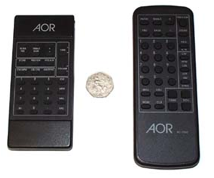
Version 2 infrared hand controller (IR7030-2)
The AR7030 has been supplied with an infrared hand controller since its initial launch, the part is referred to as "IR7030".
|
From production toward the end of 2005, we have started to use the V2 IR7030 in new production receivers, it is referred to as IR7030-2. The replacement unit is slightly larger in overall size but has significantly larger buttons (many customers requested this change). The command code is slightly different for the V2 IR7030 (header address), so the AR7030 CPU version of the receiver has to match the IR7030 in use. To keep things simple, the original radio firmware for the IR7030 starts with the number "1" (currently 14A and 18B). Firmware to support the V2 IR7030 starts with a number "2" (currently 20A and 20B). There is NO DIFFERENCE in features or performance between firmware 1x and 2x. |
The AR7030 infrared protocol listing contains details for both types of firmware / IR7030 / IR7030-2.
TOP
Tuning speed
The tuning rates are given in the AR7030 operating manual technical specification section 2, page 33:2.655Hz in SSB modes, 10.62Hz in AM & NFM modes).
The minimum tuning step size is quoted in section 5-3, page 9 as:
Increments as small as 2.655Hz
Infrared control step size rage is stated in section 5-29, page 12 as:
2.7Hz to 50kHz with auto-repeat if the TUNE key is held for more than half a second
Keypad frequency resolution is stated in section 5-39, page 13 as:
+/- 1.4Hz
The gaining or loosing of a digit is noted in section 6-4c, page 17:
Note: The receiver stores all of its frequencies in binary steps (the AR7030 doesn't think in decimal!) and as a result the last digit of the displayed frequency may gain or lose 10Hz especially if the TUNE keys are used repeatedly. This is because the step size cannot be stored as an exact number of kHz.
Additional comment added 15 May 2002, particularly in respect of use with very narrow filters (125Hz)
The Alps tuning encoder has a quoted output of 100 pulses per revolution. The Bourns part used in the AR7030 Plus has a rate of 128 pulses per revolution. There is however more to the tuning than manufacturers quoted specification.
The encoder has two outputs that are 90 degrees out of phase with each other. This results in four changes of state that the AR7030 is able to detect and use to increment/decrement the frequency by the minimum step size of 2.655Hz with each change of state from the encoder. This gives a tuning rate per complete revolution of the tuning knob in SSB mode of 400 x 2.655Hz (1.062kHz) for the Alps encoder, and 512 x 2.655Hz (1.359kHz) for the Bourns encoder. In reality, the lack of precision from the Alps encoder results in missed pulses, and the ability to carefully tune an individual pulse is very difficult. Thus despite the slight increase in the number of pulses from the Bourns unit per revolution, precision tuning is still much easier. Tuning individual increments does however require a fairly steady hand and the best way to tune in very small increments is to use the up down keys of the remote control with the step size suitably set.
TOP
AR7030 die-cast box excluded from production
The larger of the die cast boxes is absent from productions of the AR7030 beginning with serial number 10205. The decision to omit the box was taken because of the stress it places on the PCB, particularly around Q47. We have always been aware that the level of emission from the DDS system was low, however before deciding to omit the box, extensive testing of the receiver was performed to check for the presence of any additional spurious radiation that may result.The test proved interesting in that the absence of the box actually slightly reduced noise picked up by the receiver in several cases and produced no significant change in the level of the known spurii present in the set.
Subsequent production following the run for which this change was originally implemented will actually have the mounting points for the large die cast box removed but for first production batch following the change the board still has the outline and fixing points present.
TOP
AR7030 LCD back light
The back light and transistor Q77 'divert' approximately 200mA of current away from the main 5V regulator. Q77 does most of the work here so even shorting out the back light LEDs only makes a few mA difference. No operation appears to be affected by this. To do this simply short BLA and BLC on the joints between the main and front boards. This is the solder pads on the underside of the radio which connect to the PCB area of the volume control... they are accessible just be removing the bottom case half with the letter legends printed on the edge of the vertical microprocessor PCB. These terminals could be made open circuit but the main regulator would have to dissipate the extra heat produced by the extra 200mA (which it is capable of doing but shouldn't be necessary).Alternatively, add a resistor between BLA and BLC to divert some of the current from the back light LEDs to enable the display to be lit dimly to allow easy reading of the figures. I've found a values around 33ohm suitable. Warning; the resistor will be passing the majority of the current here and will need to be 0.5W or more. It will get quite warm.
TOP
AR7030 TCXO frequency reference alignment
The AR7030 excellent stability is derived from a TCXO at the heart of the receiver. This reference is aligned during manufactured using an oven-stabilized reference which in turn is periodically referenced to an on-air reference... accuracy is extremely good.Occasionally AR7030 operators comment on a 10Hz to 20Hz displayed frequency error on the higher bands, as this does not affect reception in any way, we would strongly advice that the reference is left well alone! However, for your information, the following alignment information has been extracted from the SM7030 service paperwork:
4.1 Reference Oscillator
The frequency stability and frequency accuracy of the entire set, except for the real time clock, is dependent on the Reference Oscillator. It consists of a temperature compensated xtal oscillator (TCXO) running at 11.13625MHz and a buffer stage Q46. It supplies a reference to the CPU, DDS systems and Het multiplier.4.2 Heterodyne Multiplier
The Heterodyne injection signal is derived from the TCXO and multiplied by Q46 producing a comb of strong harmonics. The fourth harmonic at 44.545MHz is selected by the tank circuit TC2, C64 and L29 and fed into the 2nd Mixer, Q20.The frequency accuracy of the receiver is dependent on a frequency measurement of the local oscillator. The meter used for this measurement should have an inherent accuracy better than +/- 0.1ppm, and the adjustment accuracy should be better than +/- 30Hz. These limits will ensure that the receiver is accurate to +/- 0.5ppm.
ADJUST REFERENCE FREQUENCY
Set AR7030 to 30.00000MHz, AM, PBS 0.0Local frequency : 75.00000 MHz at TP7 (adjust Q45 TCXO)
Note: If the frequency error is more than a few kHz then it is possible that the local osc PLL is unlocked.
Adjust L50 / L51 for 14.0 to 14.3V on TP5.
TOP
AR7030 Audio coloration
There have been a few reports of audio coloration and the matter has been investigated at length. WITHOUT AN AERIAL testing produces the most apparent difference when switching between USB/LSB especially when using the 2.1 and Collins SSB filters, this does not really affect ultimate sensitivity / selectivity, the measurement being less than 1dB.The TCXO reference and AGC calibration table have been cross-checked against our records during realignment and confirm that ageing and alignment are not a problem. The degree of coloration does vary between AR7030, some are almost perfect in this respect but still they vary with temperature from switch-on. We have eliminated the most obvious potential problems such as carrier injection point & carrier filter, filter measurement resolution (which is 33 Hz resulting in any error less than 16.5 Hz), misalignment of TCXO etc. It is simply a characteristic which varies between sets.
We can advise with confidence that the coloration is purely due to filter asymmetry... there are effectively 5 filters forming a cascade in the 45 MHz I.F., it doesn't take more than 100 Hz asymmetry in any one filter to cause "coloration" of audio.
As the carrier and main audio always pass through the center section of filters, the recovered audio is always good. The AR7030 has particularly been designed to offer good close-in strong signal handling, for this reason the user selectable (tight) filter is toward the head of the cascade... this provides high performance. However in the absence of a signal, wide band noise plus that generated in the receiver's I.F. can pass down the I.F. cascade and on to the audio amplifier.
It only takes 100 Hz or so of asymmetry to generate uneven coloration... this is not surprising as no ceramic filter is perfect as different physical attributes generate each filter edge. As the audio is inverted between side bands, accentuation of high tones on USB would become accentuated low tones on LSB. Adjusting the PBS just a touch changes the coloration and the AR7030 has been designed to ensure that the PBS is held separately in "each" mode.
The signal path is as follows (total of 5 filters):
1. Two roofing filters 45M1B
2. User selectable filter
3. CFU455G2 tail filter
4. Final tail filter. CFU455IT (4 kHz) for narrow filter selection, or CFU455G2 for wider filter selection.
When using a narrow SSB or narrow AM filter, changing the CFU455IT made the largest improvement in audio coloration, however the exact coloration depends to some extent on temperature - for this reason it is impossible to be "spot on" all the time!
Swapping the standard SSB filter of fitting to a Collins MF2.5 has no real effect, but changing the CFU455IT did, the coloration of both side bands became quite similar on our test unit.
The AR3030 generally is much worse under this test with different audio coloration obvious even under real signal ECSS tests and different s-meter readings between side bands.
TOP
AR7030 PLL lock times
The response time of the AR7030 to an input frequency change varies on the size of shift and if it crosses over into another VCO range. The actual lock times below have been taken from a random set taken from production.The first PLL lock time has been taken as the time between a frequency change instruction being given from the sets microprocessor and a lock signal being received back at the microprocessor.
The second time given is the time taken to receive full audio output (AGC off) for the same input instruction.
| Lock signal | Audio signal | |
|---|---|---|
| Close frequency change (100KHz) | 50ms | 100mS |
| Medium frequency change (1MHz) | 100ms | 60ms |
| Wide frequency change (VCO range end to end) |
200ms | 140m |
| Wide frequency range (change of VCO range) |
400m | 200ms |
Note: An additional time between an instruction being given at the front panel and the micro sending an instruction to the PLL are:-
| Approx.' 1ms from a frequency change at the main encoder. |
| Approx.' 80mS from an instruction from the remote IR hand set. |
TOP
AR7030 noises and AGC pops
Two customers have reported 'popping' on MW although I cannot say that we have duplicated the effect in the workshop (so remains something of a mystery)... one customer was in Sweden and the other in Japan.The Swedish Customer suggested the following component changes:
| Change C104 to 3.3uF |
| Short R94 with a jumper |
The Japanese customer carried out this change and was happy with the result.
You may notice a change when fitting the UPNB7030 too as an additional filter is employed on the UPNB7030 for the spike detection of noise, this will change the audio properties to some extent, in fact there is a slight drop in audio bandwidth (almost unnoticeable in fidelity) but will help quash high frequencies, some customers have commented that they prefer the tone.
The volume, treble and bass controls of the AR7030 are digitally selected by the audio amplifier, there are no external components employed, all the features are provided directly by the audio amplifier IC. As the device acts digitally, there is a finite number of 'steps' employed. Unlike analogue tuning controls which may be infinitely varied, the audio amplifier 'switches' in steps of 1dB and 2dB. Even the resolution of step size is determined by the audio amplifier IC and cannot be altered to provide finer resolution. It is possible to hear 'clicks' and similar anomalies in certain areas of tone and volume setting due to the IC switching process, this cannot be eliminated.
In a similar manner, the FILTER switching momentarily changes the input/output impedances of the I.F. chain, in addition the carrier insertion oscillator is moved to optimize each individual filter. A 'click' results from this process but cannot be removed. Furthermore, as the user selectable filter is unconventionally placed well up the front of the I.F. path (to provide good close-in selectivity), the full audio bandwidth is left to propagate down the I.F. chain, any stray noise may appear amplified. The noise when switching filters is more pronounced on earlier versions of the CPU firmware, the routines employed in the later releaser have been revised to further reduce 'clicks' when switching filters.
TOP
AR7030 LCD noise
Productions from Y2000 onward of AR7030 had the later LCD fitted, this is 'RF quieter' than the original LCD (so does not require the earth strap), of course, like all displays, it does still produce noise in some parts of the spectrum. When running from an earthed bench supply, virtually all of the noise is eliminated. We would certainly recommend adding an RF earth to your listening environment, even a connection to a cold-water pipe or central heating radiator will be a great improvement, an earth spike (tent peg) when truly remote from home.The earth strap is NOT fitted to the later LCD type during production,
the metal display holder is painted which makes adding such an earth strap difficult (the benefits are not worthwhile, simply add a good RF earth to the radio earth point on the rear case). Out of curiosity, before changing supplier of LCD, we applied an additional earth strap to the LCD (by scratching the paint off)... the change in noise level was virtually nil. As the metal surround of the later LCD is painted, it has not been practical to apply the additional earth strap (but the noise level of the later LCD is generally the same as the earlier type with strap fitted).
AR7030 Earth modification to LCD (not applicable to later LCD types)
The LCD on the AR7030 produced a small amount of noise which can be picked up by the radio under certain circumstances. This is most noticeable at lower frequencies when using the set with an internal battery pack, a telescopic whip and no RF earth. All later sets have an extra earthing strap fitted to overcome this problem (from serial number 101713).
To retro fit this extra earthing strap, both covers and the front panel will have to be removed. 6 bottom panel screws, 4 top case screws and 4 front panel screws (2 on front and 2 behind each fitted with 2 spacers).
Once the front PCB is visible, the earth strap replaces the existing one that is fitted from the main PCB to the < > encoder. The new strap is now extended to earth the LCD surround as well.
The new strap is made from a piece of brass shim 5mm X 70mm. Shape the metal to form a curve at one end (radius; approx. 3mm). Add a thin piece of insulation to the outside edge of the radius. The curve can now be slid under the LCD screening surround without shorting the LCD contacts (the earth strip hooks around the inside edge of the display screening can and sits between this and the LCD rubber contact pieces).
Once behind the LCD screening, the rest of the strip can be shaped over the < > encoder and bent around the front panel to enable soldering onto the main board earthing point.
Replace the front panel and case halves.
TOP
AR7030 side rail replacement (top case screws stripped)
Despite a warning in the AR7030 operating manual and fitting sheets to 'not over-tighten' the top case screws, several customers have reported problems re-securing the top case because the screws / side-rail threads have stripped. It helps to fit the top panel BEFORE tightening the bottom case half. All current production of AR7030 uses 'drilled & tapped' longer screws which helps longevity.There are two ways to 'revive' the top case / side rail fitting:
1 - best method:
Drill the side rails with a 3.8mm drill. Tap the holes with a M4 tap. Fit longer screws (M4x12). Ensure the side rail holes are central to the holes in top cover. Ensure all drilling swarf is caught and removed from the radio.2 - crude method:
We are not too comfortable suggesting this as a method to resurrect stripped threads... remove the side rails from the receiver, belt the side rail (using blocks of wood to prevent marking) with a hammer to close the grove a bit more !TOP
AR7030 key bounce
A number of reports have been received relating to key bounce, especially when switching off the receiver (it switches back on again). This report is related mainly to earlier CPU firmware versions.There is an anti-bounce routine encoded for the keys within the CPU firmware, however this did not take account of a potential for simultaneous 'make' and 'break' bounce. The later CPU versions were revised in this area. Side effects of the key-bounce included the set switching back on and menus changing on their own volition (AGC and filter values changing).
As the AR7030 front keys age, they become dirtier in operation, cleaning them is quite easy but needs some careful handling. Removal of the switch 'head' involves squeezing the two plastic clips on either side of the switch (watch out that the spring and inner pieces do not get lost). Locate the contact plate, strangely, only one side is ever tarnished, either reverse the plate or clean the dirty side with a fiber-brush. Reassembly is easy but ensure that all parts are offered up squarely so they do not get bent in the process. Of course it is possible to replace the switches but only the 'tops' and 'contacts' need replacing... de-soldering of the switch would otherwise require complete dismantling of the control board.
TOP
Spurious 'fast charge' LCD message
The 'fast charge' message can sometimes appear as a spurious message (when you do not have the optional internal battery BP123 fitted).Occasionally when a power transient is encountered (thunderstorm), the microprocessor 'thinks' it has detected an internal battery but of course it needs charging as the voltage measures zero Volts !!! It then attempts to 'fast charge' the phantom battery without success.
The 'fast charge' message will remain on the LCD for about 2 hours... just switch the receiver OFF but leave it plugged into power. You cannot cancel the message or fool it by switching on/off or unplugging or the 2-hour period will simply start over again, patience is required.
There is no harmful effect of the message, ignore it unless it keeps cropping up all the time.
TOP
AR7030 backup NiCad
A NiCad backup battery is used to maintain the volatile data of the AR7030 (VFO, clock etc.). The AGC calibration table and memory channels are held in EEPROM so should not be lost even if the NiCad fails.It appears that after a few years, occasionally the NiCad does not like to be left un-powered for periods in excess of a week or so, they have been known to 'whisker' and fail... similar to computer BIOS support batteries.
The NiCad is 1/3 AA PCB MOUNTING, the voltage is 1.2V (single cell).
Replacement is fairly straight forward, make sure the set is disconnected from supply (not just switched off) as the CPU goes into standby mode while still powered and you could really corrupt the operating system if it remains powered.
Be careful not to 'fry' the nearby SMD components, otherwise it is possible to remove & replace the NiCad from the inside of the radio cabinet without removing the front panel (the hole clearance is large enough).
Occasionally it is necessary to PRESET & TEST to clear the data (if its corrupt) using the SM7030 service kit software. Basically use the 7030TEST.EXE DOS program from the SM7030 service kit (it runs in a window fine).
| 1) Logon / Setup Debug [ENT] |
| 1) Logon to receiver [ENT] |
| 2) Preset and test memory [ENT] - warning, enter 1 to continue [1] [ENT] |
| 0) Return to main menu [ENT] |
| 5) IF system & s-meter [ENT] |
| 3) View / edit 's-meter cal values [ENT] |
|
1) ENT 60 [ENT] 2) ENT 10 [ENT] 3) ENT 20 [ENT] ... ... 10) |
|
[0] [ENT] [0] [ENT] [10] [ENT] In the last section above, substitute YOUR cal values for those in the example. |
Carry out a filter re-calibration from the radio CONFIG menu and remember to enable any options such as ATTENUATOR step (PLUS unit) and NB7030.
Nothing else should be required... but of course your memory locations will be completely empty so you will have to 'manually' start filling your memories again.
You can download an extract of the software on this link: click here
NOTE IF USING WINDOWS XP:
(unlikely to work on Windows versions after XP.)
If you get an error message while carrying out the preset & test, it may be a PC compatibility issue rather than a hardware fault with the radio.
Presetting memory ..........
Additional EEPROM .........................
Checking RTC/RAM
Error in data after 2 bytes.
Press ENTER to continue.
The error may by "1 byte" or "2 bytes" depending on how many times you have run the software. This is probably a communications failure due to XP on your PC. The 7030TEST.EXE software runs under XP but is rather sluggish.
However, the preset & test part of the program fails on most XP machines (presumably due to poor timing / synchronization). The RS232 serial port on XP systems is treated as a network device rather than a hardware/BIOS legacy device, even booting XP into a DOS window with compatibility setup or pseudo–DOS SAFE MODE will not help.
If you have an older PC with DOS_5/6 or Windows_3.1x/95/98/ME it will work fine.
Otherwise make a W98 boot disk and add the 7030TEXT.EXE utility to the floppy disk (you may have to delete the README and CD-ROM drivers from the boot dusk for the AR7030TEST.EXE utility to fit).
Boot the XP PC from the W98 floppy and select NO CD-ROM support. Ignore any messages about the hard drive... you may have to temporarily change the BIOS boot sequence to enable you to boot from the floppy disk.
When booted, type in 7030TEST and hit enter, you should be able to use the software okay.
Afterward, remove the floppy and re-boot the PC as normal.
TOP
AR7030 Clock
The AR7030 displayed clock is referenced from a 32.768KHz crystal, X1 which can be found on the rear of the front control panel (remove top cover to view).It is adjustable by trimming capacitor, TC1 next to it. This is adjusted at the time of manufacture and shouldn't need any further adjustment.
As the emphasis within the radio is towards RF performance, the clock function is regarded very much as a secondary function and as such does have its limitations.
The clock crystal is a simple device, it doesn't have any temperature compensation or other such circuits to improve its accuracy.
The surrounding ambient temperature, length of periods the set is in use and any other factors that alter the temperature within the radio will therefore affect the accuracy of the clock. The accuracy of the clock, at best, will always be a compromise.
During production, the clock xtal is set up after several days of use with the set at maximum operating temperature. The clock is set slightly fast at this point as the radio is unlikely to be subjected to such a high average temperature in use after this initial soak test period. Even the most intensely used set is likely to be switched off for at least a few hours a day. The clock should therefore keep reasonable time in a set used perhaps a couple of hours a day and kept at room temperature when not in use.
Ideally the clock should be set up in the users environment at its average temperature. Clearly this is not possible.
During set up, the actual clock 'period' is counted rather than the crystal frequency measured. This is not practical in for most people without the use of expensive test equipment, so at best, a frequency counter could be used (taking care not to pull the frequency). Alternatively, TC1 could be adjusted by trial and error monitoring the clock over a fixed period of time.
Warning – TC1 requires very delicate adjustment. The chances are that, after adjustment, the clock will be a lot less accurate than before adjustment! Proceed with care.
TOP
BP123 battery option problems with later serial numbers
In 2000/2002 we have received a few reports of problems with power-up / power-down (LCD behaving strangely) after the BP123 battery option has been fitted. Only later serial numbers have produced this problem, we assume it is due to component tolerances as there has been no change to key components or production methods.The 'text' from the bulletin is presented below, the PDF file provides a simple location drawing for the component position and repeat of text:
|
We have had one report (now two) of an AR7030 failing to power down from the front panel when using a BP123 battery option. The fault shows various symptoms, when switching the set off, it may switch itself back on again after a couple of seconds or at worst, lock up completely. This does not occur when the normal power supply is used with the set. The problem appears to be confined to newer sets. Older sets have no problem regardless of the age of microprocessor fitted. Newer sets appear to be OK with 12A microprocessors (an unlikely situation) but may display the problem with 14A, 16B and 18B versions. The problem appears to be due to the switch off delay (or its decay) time of the 5V line supplying the microprocessor. No changes have taken place with the programmed delay time, so differences must be due to manufacturer changes or tolerance differences within components in later sets. Different micro batch codes may also be a factor. The problem can, however, be easily overcome by the addition of a small delay in the supply switching control line. This is done by the addition of a 22uF capacitor between the junction of R231 / D55 to ground. R231 is located close to the battery connector, J11, just in front of relay, RL5. Connect a capacitor between the end closest to D55 and any suitable ground. Click here for the 11kb PDF file |
Revised text March 2002On some later AR7030s, problems may arise when the optional battery pack, BP123 is fitted. The problem shows up with the symptoms that the set powers itself on and off a couple of times or at worse enters this cycle continuously.The problem may show in three ways;
In all of the above cases, the set will recover itself by operating the power switch. Do not, however, confuse the problem with simply having a flat battery. The reason for the problem is not actually a faulty component but is due to changes in component manufacture used during the various production runs of the AR7030. Two simple fixes can be added if the problem is encountered. 1) The easiest fix which is detailed above, which will cure most cases, is simply by adding a 22uf or 47uf capacitor between the junction of R231 and D55 down to ground. 2) A more comprehensive modification is effected as follows; Cut the +5C supply track at a point around C212 (next to the rear panel, close to the contrast spindle) – this feeds pins 15 & 16 of Q81, 82 & 83. Now add a suitable diode bridging the cut track (suitable points to solder are from the supply side of VR4 and to pins 15 & 16 of Q81 - Anode towards VR4). Fit a resistor across the diode – 10k should do. Although virtually any diode will do the job, a 1A shottky device has been used purely because it is an easy size to handle and the resultant voltage drop is relatively small. Fit a capacitor from pins 15 & 16, Q81 to ground – a 220uf will do although a 470uf can be fitted to be really sure. A resistor can also be fitted across the capacitor (10k) This can all be done very neatly with the diode and resistor running under the contrast spindle. The spindle just pulls out while working in the area. A suitable earth point for the capacitor can be found next to R84 just above X12 – this is a feed through hole, so the cap leg can feed through the board and be soldered on the other side if a small amount of resist is moved from the underside of the board. |
Remember, to switch the AR7030 on/off using battery, the power switch must be held for a second or two, not just quickly tapped.
TOP
EEPROM corruption of AGC table
It is possible for the AR7030 AGC table (signal meter calibration) to become corrupt if power is removed from the radio while under computer control. It is important that the PC control software is terminated and the radio switched off from its front panel switch (do not just pull out the power connector or remove supply). Potentially power transients / brownouts could cause similar problems, but this is speculative.If the table cannot be read by the microprocessor or does not exist, the radio automatically loads DEFAULT DATA so that the receiver at least has a change at operating normally However, if the table exists but is corrupt, it is possible that the radio will behave strangely (incorrect signal meter or the attenuator switching inappropriately).
It is possible to re-enter the correct AGC calibration data using the SM7030 service kit (7030TEST.EXE) software which operates on a PC in DOS mode (it will run in a window under MS-Windows). (unlikely to work on Windows versions after XP.)
It is possible to download a ZIPPED file comprising of a PDF bulletin on the subject along with the EXE program and supporting documentation. Please note, the content is subject to copyright (c) AOR LTD 2002 and must not be copied or published for any reason other than for addressing the issues outlined here. By downloading and / or using the file, it is assumed in law that you accept this condition, the software carries no warranty. click here (120 kb).
If you are using WindowsXP, take a look at the comments in the NiCad battery bulletin - click here
(unlikely to work on Windows versions after XP.)
TOP
Power consumption - standby
For critical applications, a few customers have requested power consumption figures for operation from the a.c. mains power supply (via power invertors) and when running from d.c.Operation via the a.c. supply
Current drawn from a.c. mains via the AOR standard PSU (230V version used for this test):| With a standard AR7030 connected and switched to standby mode | 48mA @ 230V a.c. |
| With an AR7030 PLUS connected and switched to standby mode | 49.5mA @ 230V a.c. |
| Power supply only with no radio connected | 46.5mA @ 230V a.c. |
| Power supply with an AR7030 in normal operation | approx. 70 to 80mA @ 230V a.c. |
Operation via a d.c. connection
Current drawn from a 15V d.c. power supply:| With a standard AR7030 connected and switched to standby mode | 28.2mA @ 15V d.c. |
| With an AR7030 PLUS connected and switched to standby mode | 48.9mA @ 15V d.c. |
TOP
AR7030 'sluggish' behavior - infrared remote contamination
The two items from the subject heading are not identical but are loosely connected.Sluggish behavior of AR7030
A few reports have been received suggesting that the AR7030 occasionally behaves in a very sluggish manner where button presses and tuning appears to act in slow motion with little or no response possible from the infrared remote. Luckily we have experienced this characteristic with other consumer products so the solution was not difficult to find.The AR7030 has two infrared remote sensors, one on the front cabinet and one on the rear. Under certain situations, it is possible for the infrared sensor to become 'saturated' by energy of a similar waveband, this includes the morning (red) sunrise at low angles, the setting sun (red) at low angles and low energy RF energized fluorescent lights.
If this presents a problem at certain times of the year / light levels, mask the infrared sensor which is facing the light source with a piece of black tape or relocate the radio or lamp.
The swamping of infrared causes the AR7030 microprocessor to work overtime trying to decode the infrared signals (which it can never do because they are not true infrared codes). This results in the AR7030 responding very slowly to other inputs.
Contaminated infrared control hand unit
We received a report in Dec'01 of the AR7030 hand unit not functioning correctly, it was sending the same AM/Sync signal regardless of which button was pressed. We suspected that the infrared control had become contaminated (someone once dropped one in hot sweet tea - it needed a really good clean afterward to restore operation).Following careful cleaning (carried out by the customer following our instructions below - as the unit was out of warranty), normal operation was restored to the hand unit, the customer was very happy again. The text of the e-mail is presented below as it may be of assistance to others. The hand unit is relatively inexpensive as a spare part:
To-date, we have only experienced one similar report. On that occasion, the remote control was 'contaminated' internally causing the keys to operate on their own... the customer purchased a new remote and everything was fine.
As an experiment in the workshop, if the AM/Sync key is held down, all following keys caused the AM/Sync signal to be transmitted again. This remote sends ONE BURST of signal when the key is pressed then stops sending. If there is no external sign of the key being permanently depressed, consider internal investigation. On the basis of 'you have nothing to lose'... you may wish to open the remote control and examine the keypad membrane (it's not easy to gain access).
1. Remove the battery cover.
2. Remove the batteries.
3. The front / back of the cabinet is held together with lugs, there are two in the bottom, two in the top, one on each side plus numerous smaller lugs.
Stand the remote on its bottom edge so that the battery compartment is next to the desk top with the front printed letters 'AOR' facing upward and away from you. In the very bottom (below the bottom battery), there are two access points which can be used to prize the rear cabinet from the front cabinet. Generally work around the rest of the cabinet until it is completely apart using a TWISTING action... you will note that the top IR window stops the top cabinet halves from easily separating.
4. The PCB is held in place by two small lugs on each side-edge. Remove the PCB to access the keypad membrane.
5. Look for any signs of contamination on the membrane and PCB. We once recovered an IR control after it had been for a swim in hot sweet tea!
6. While the PCB may be cleaned with isopropyl-alcohol, do not use any chemical to clean the membrane as it is simply carbon printed. If it is contaminated with a liquid, simply clean with water for a very brief period.
7. Partially reassemble the keypad and PCB so that contact is made with the battery connections. Re-fit the batteries and test. If all is working, re-build the remote and re-test.
We cannot totally discard the possibility of a fault with the radio itself, but this is very unlikely and would be the very first instance of such a failure. It would be great if you could test the radio with another AR7030 IR or check your IR on another AR7030.
snip
TOP
AR7030 AUX / REMOTE accessory power feed
The AR7030 has 14V available on the rear panel AUX and REMOTE connectors (refer to the AR7030 operating manuals for exact pin-out information).Both outputs are fed from the same internal supply line via a fuseable 22 OHM 0.5W resistor (R237), so the total current via the resistor is limited to 100mA, not 100mA per connector.
The fuseable resistor is not self-resetting, if damage, it will need to be replaced. The resistor is intended to prevent serious damage to the radio in the event that the accessory supply is shorted (low voltage directive, part of the CE approval).
TOP
FM7030 - VHF stereo FM option
The AR7030 has been designed with a stereo signal path to the front panel headphone output and rear panel AUX socket, this was 'designed-in' to allow the later fitting of an optional Band-II FM receiver board. Initially there had been considerable interest expressed in such an extended coverage board, especially in the USA with the Drake SW8 being an example.The Band-II receive board was intended to address a niche market providing high sensitivity and selectivity with RDS ident display offering the Band-II DX'er "real performance" instead of using standard Hi-Fi tuners or wide band receivers.
Shortly after release however, interest in such a receive board almost completely dried up, particularly when considering projected price against development cost and the potential small market.
TOP
Tape record relay specification
The AR7030 has the ability to provide audio for a tape recorder and DC motor switching via the rear panel AUX 8-pin DIN connector. In particular, pin 6 & pin 7 provide independent relay contacts (made when a signal is present and squelch is open). The relay 'contact' specification is 24V DC at 1A maximum. The AR7030 is NOT intended to switch a.c. mains supply (100 - 230V).TOP
Unequal audio through headphones at low volume
The line amplifier is used to drive the front panel headphone socket (not the main audio amplifier). The line amplifier drives left and right channels independently and supplies both the front panel headphone socket and rear panel AUX socket. The level to the AUX socket can be configured through the CONFIG menu.When using sensitive headphones, you may notice that the left/right volume level becomes unequal at low volume settings. In fact when the audio is turned off completely, one channel may still be just audible. This is due to a small amount of cross-talk within the receiver. To improve the characteristic, lower the volume levels in the config menu to 70% or less (the default is 99%). This is a compromise of design and is not considered a serious issue - but a few customers have noted the effect.
TOP
Mute / transmit considerations
Pin-1 on the AR7030 AUX socket must be grounded to mute the AR7030 during transmit. The mute line performs two functions:| 1) Mutes the audio (it also stops some of the control functions from operating). |
| 2) Causes the AGC line to go high, this desensitizes the receiver. The signal meter 'freezes' close to its previous reading during mute. |
Reservations:
The AGC isn't applied until relatively late in the receivers signal path. The front end (SD5400 mixer) is still open to the full RF signal from the transmitters aerial. Designing a circuit to ground the receivers aerial input when transmit occurs would be a better solution (in addition to applying the mute control). Useful points would be...| a) Mute line, normally 5V shifting to 0V when muted. |
| b) Pin-34 of the AR7030 microprocessor, inverse of mute live, 0V, 5V muted. This should be capable of providing the switching level for an 'RF mute' circuit. |
TOP
VLF sensitivity
It is true that the AR7030 will tune down to 0 MHz, the microprocessor is not disabled to prevent such tuning, however when you drop below about 6 kHz, the receiver's local oscillator becomes audible producing near full scale deflection of signal meter. Reciprocal mixing will increase close to the local oscillator but is "so clean" (when compared to receivers in the same class and many times more expensive), it does allow reception well below 20 kHz.For the above reason, it is not possible to tune to the receiver below 6 kHz with a wide filter, you must also bear in mind the mathematics when considering wide filters - a negative frequency below 0 MHz cannot be monitored!
The published specification suggests sensitivity down to 20 kHz of (1.9uV/1.4uV preamp off/on).
Further measurements in the UK workshop of a typical unit (in fact several were measured) produced a variation of about 6dB at extreme LF due to component variation. Results for 20 kHz, 15 kHz, 13 kHz and 10 kHz are as follows (preamp off, switching the preamp on increases sensitivity very slightly but introduces additional noise):
| 20 kHz SSB S+N/N | -96 dBm 3.5uV preamp off |
| 15 kHz SSB S+N/N | -75 dBm 40uV preamp off |
| 13 kHz SSB S+N/N | -65 dBm 120uV preamp off |
| 10 kHz SSB S+N/N | -51 dBm 600uV preamp off |
Receiving equipment for dedicated LF reception of atmospheric and ground movement (earthquake 174 Hz) requires radically different engineering, however the AR7030 should produce very useful results down to about 10 kHz.
If the input transformers were to be replaced with more LF specific designs and if you were willing to sacrifice the long wire input and whip amplifier, further improvements could be made at LF. The input capacitors and chokes are all too small for LF as well and should be replaced.
TOP
Please note that the information is supplied “as is” without any support nor obligation. This model is no-longer accepted for repair and none of the parts are available anymore.
www.aorja.com