AR5000 SERIES BULLETIN PAGE
Archive originally from the AOR-UK website in 2008, edited in 2021 by AOR Ltd. In Japan.
This information is supplied as a convenience to our loyal customers still using discontinued legacy AOR receivers.
Some pdf files linked in this archive might mention old contact details for AOR-UK, AOR-USA and AOR Ltd. These are not valid anymore and can be ignored.
Please note that the information is supplied “as is” without any support nor obligation. This model is no-longer accepted for repair and none of the parts are available anymore.
AR5000 brief production history
The AR5000 first appeared in 1996, the serial numbers were 5xxxx (six-digit numbers starting with the number five). In the first few months of production, some beefing up of the internal power PCB took place, a trimmer was added to the SSB insertion oscillator (PCB) and some noise reducing changes added (DDS decoupling, change of RS232 device).A revision to operation (firmware) appeared after about one year, the serial numbers changed to 07xxxx (six digit numbers starting zero seven with four digits following).
A board change occurred around serial number 070661 when the AR5000+3 additions appeared (Synchronous AM, noise blanker, AFC).
Around 070661 the EEPROM switching was revised so that an alternate bank of memories and search banks could be switched (doubling the memory capability).
Minor firmware revisions have taken place since, mainly to boost the durability of EEPROM when under computer control (commercial operators).
The AR5000C was a frequency coherent version of the AR5000, designed for commercial operators.
TOP
AR5000 1kHz filter modification
We have had several enquiries regarding the fitting of a 1kHz data filter to the AR5000; in particular the CFJ455K8 which we originally sourced for our AR7030 HF receiver. The main problem in fitting this filter to the AR5000 is the physical incompatibility; we have found however that by turning the filter upside down you can attach short leads to it and connect it in the MF1 Collins 500Hz filter position on the AR5000 IF board without any great difficulty.The diagram below shows the CFJ455K8 filter connection details. All three earth connections should be connected together using tinned copper wire and then soldered to the original Collins earth connection using thick tinned copper wire to achieve a good physical stability on the board. Short lengths of wire can now be used to make the in/out connections between the filter and PCB. If you require a more permanent fixing of the filter to the board we suggest double sided tape to hold the filter in an upside-down position before making the soldered connections.
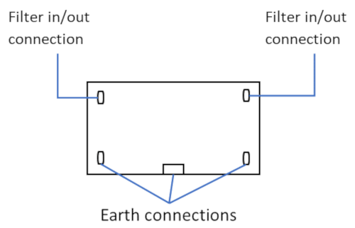
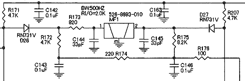
Careful examination of the PCB around the filter connections will show that there are two 33pF SMD capacitors connected between the filter in/out and earth. Ideally these could be removed to give a flatter frequency response along with changing R173 to 1k8. In practice however you will probably not notice any change and we recommend that they are left as standard. The circuit is shown below
After fitting the filter, refer to page 68 and 69 of the AR5000 instruction manual in order to register the new filter. You must register the new filter as a 500Hz filter - this is also the bandwidth that will be displayed when the filter is selected. Unfortunately there is no 1kHz bandwidth available on the display.
TOP
AR5000 DETECTOR OUTPUT
The AR5000 is capable of running various decoders from its ACC1 socket on the front panel (pin2 gives approx. 180mV RMS -100Kohm).This is suitable in most cases, but is slightly limited by two 0.1uf capacitors and switching circuits in line between the detector output and the socket.
If problems are experienced, then the solution will probably be direct connection to the FM detector IC on the IF unit.
To do this, remove the top case of the receiver to reveal the IF and PLL units underneath. The IF unit is the rearmost board (fitted with various filters). Once the six screws are undone and the IF OUT mini-coax plug disconnected, the board will pull slightly forward and hinge towards the front panel.
The detector output can be taken from pin 9, IC8. This is a surface mount IC located on the underside of the board (roughly under the 10.245Mhz crystal).
IC8 is labelled as MC3372M.
The output can be taken by directly soldering a wire to the output pin or from the capacitor it feeds (C88 - located directly next to pin 9). Care must obviously be taken when carrying out any work of this type. Note that there is a small DC level present on this pin and some DC decoupling will be needed if none is present in the decoder input.
As all pins on ACC1 socket are used, the new detector output will now have to brought out of the set separately or possibly connected to pin 4 on ACC2 if that socket is not being used.
Refit the board and test before re-fitting the top cover.
Approximate output levels to be expected directly from the IC are (with a large signal input and 1kHz tone):
| Filter used | Deviated at 3kHz | Maximum deviation for filter bandwidth |
|---|---|---|
| 6kHz | 900mV (p / p) | 1.2V (p / p) |
| 15kHz | 600mV | 1.2V |
| 30kHz | 300mV | 1.2V |
| 110kHz | 200mV | 1.2V |
TOP
Further specification - measurements
The following additional specification has been generated at the request of customers, much of the test data has been provided by AOR Japan and represents 'typical' measurements:Maximum signal input:
+17dBm input is acceptable without damage over the entire frequency range of the AR5000, this represents about 1.5V into 50 OHMS.AGC time constant:
| FM | ON/OFF |
| AM, USB, LSB, CW | OFF / SLOW |
AFC (AR5000+3 only):
The AFC operates in AM, & FM modes, it is not operational in SSB modes. Operation typically auto-tunes to center frequency within a few seconds when an offset of a few kHz exists. The maximum capture offset is 25kHz.Overall noise figure:
AM S/N is as follows at 60% and 70% modulation with 3 kHz and 6 kHz filters| Freq | Filter | 60% | 70% |
|---|---|---|---|
| 129.8 MHz | 3kHz | 48dB | 49dB |
| 129.8 MHz | 6kHz | 49dB | 50dB |
| 880.8 MHz | 3kHz | 33dB | 33.5dB |
| 880.8 MHz | 6kHz | 46dB | 47dB |
IF / image rejection, Image rejection (1st image):
| 250 kHz | 81dB |
| 700 kHz | 81dB |
| 1.450 MHz | 85dB |
| 3.000 MHz | 85dB |
| 7.000 MHz | 87dB |
| 15.80 MHz | 88dB |
| 30.80 MHz | 89dB |
| 52.80 MHz | 107dB |
| 120.8 MHz | 119dB |
| 199.8 MHz | 95dB |
| 320.8 MHz | 76dB |
| 430.8 MHz | 52dB |
| 850.8 MHz | 54dB |
| 1250.8 MHz | 59dB |
| 2600.0 MHz | 81dB |
2nd order products:
| Tested at 129.800 MHz (wanted signal) to produce 12dB SINAD | -118 dBm |
| Unwanted signal 2.550 MHz | - 33.5 dBm |
| Unwanted signal 132.350 MHz | - 33.5 dBm |
| 84.5dB |
3rd order products:
| Test frequency (wanted) | Unwanted frequencies | Product |
|---|---|---|
| 25.800 MHz | 25.925 & 26.050 MHz | -8dBm |
| 129.800 MHz | 129.925 & 130.050 MHz | -14dBm |
| 320.800 MHz | 320.925 & 321.050 MHz | -12dBm |
| 470.800 MHz | 470.925 & 471.050 | -10dBm |
| 850.800 MHz | 850.925 & 851.050 | -10dBm |
Cross modulation:
| Wanted frequency 129.800 MHz, 60% AM with 15 kHz bandwidth | -93dBm S/N 21.5dB |
| Interfering signal 129.900 MHz, 30% mod | -23dBm S/N 18dB 60dB -27dBm S/N 20dB 56dB |
| Wanted frequency 129.800 MHz, 60% AM with 15 kHz bandwidth | -89dBm |
| Interfering signal 129.925 MHz, 30% mod | -23dBm S/N 20dB 60dB |
TOP
There are two resets for the AR5000:
1) CPU RESET. If switching the set off/on does not help, the next action should be to reset the receiver using the hidden reset switch provided.The reset switch is located behind the torque lever to the right of the main tuning dial.
i. Move the lever to the downwards position, a black cloth material covers the slot. The reset switch is located at the top of the slot about 10mm behind the front panel.
ii. Using a match stick or similar tool, press and release the reset switch (with the unit switched on, and powered in a normal manner).
iii. The back light will extinguish then all LCD characters will be displayed, the set will then power up and resume normal operation (if it has not automatically switched on again press the "Power" button).
This will re-boot the CPU without erasing the search/memory contents or going back to the default settings. The last entered frequency in VFO may be lost.
2) CPU SOFT RESET. If the reset switch does not help, it is possible to SOFT RESET the AR5000 CPU. This will clear all bank link information and reset the VFO to default parameters including frequency display of 128.900Mhz.
i. Switch the receiver off (unplug the power cord if necessary to power down the receiver).
ii. Press and hold the "CLR" key while switching on the receiver once again, keep hold of the "CLR" key.
iii. The clock will be displayed, wait for the default frequency/text display to appear then release the "CLR" key.
The defaults are:
Frequency 128.900MHz
Receiver Mode AM
Tuning Step 25kHz
IFBW 6.0kHz
Attenuator 00dB
TOP
AR5000 S-Meter Response (HEX)
The following table is compiled using a standard AR5000 in NFM mode with the 15KHz filter fitted at 171.1MHz. The meter response throughout the VHF region is reasonably flat and will give readings of similar level. The responses were obtained using the LM command| Signal Input (dBm) | Hex Response | Signal Input (dBm) | Hex Response |
|---|---|---|---|
| - - | 02 | -85 | 7F |
| -120 | 02 | -80 | 8B |
| -115 | 02 | -75 | 96 |
| -112 | 02 | -70 | A0 |
| -111 | 06 | -65 | AA |
| -110 | 0B | -60 | B3 |
| -109 | 14 | -55 | BD |
| -108 | 1D | -50 | C6 |
| -107 | 25 | -45 | CE |
| -106 | 2B | -40 | D7 |
| -105 | 32 | -35 | E0 |
| -104 | 38 | -30 | E8 |
| -103 | 3D | -25 | F1 |
| -102 | 43 | -20 | F8 |
| -101 | 49 | -15 | FA |
| -100 | 4E | -10 | FB |
| -95 | 63 | -5 | FC |
| -90 | 71 | 0 | FD |
TOP
AR5000 Frequency stability
Measured for a ‘typical’ stock set.Measured at 20 MHz from cold. Room temperature approx. 25 degrees Celsius.
| Time Elapsed | Frequency change from start |
|---|---|
| 0 | 0 Hz |
| 1 minute | 3 Hz |
| 2 minutes | 4 Hz |
| 3 minutes | 6 Hz |
| 4 minutes | 8 Hz |
| 5 minutes | 9 Hz |
| 10 minutes | 16 Hz |
| 20 minutes | 25 Hz |
| 30 minutes | 30 Hz |
| 40 minutes | 33 Hz |
| 50 minutes | 35 Hz |
| 1 hour | 36 Hz |
| 2 hours | 37 Hz |
| i.e. | Under 2ppm from cold in 1st hour. 0.05ppm in subsequent hour. |
TOP
AR5000 Local Oscillator Phase Noise Measurements
The following measurements are from a 'typical' AR5000 receiver.| VCO | dBC/Hz 25KHz Offset | 50KHz Offset | ||
|---|---|---|---|---|
| VCO1 | 10KHz | 622.4MHz | 109 | 112 |
| 15KHz | 637.4MHz | 110 | 112 | |
| 29KHz | 651.4MHz | 109 | 111 | |
| VC02 | 30MHz | 652.4MHz | 103 | 108 |
| 103MHz | 725.4MHz | 103 | 108 | |
| 174MHz | 796.4MHz | 104 | 108 | |
| 675MHz | 1297.4MHz | 98 | 104 | |
| 825MHz | 1447.4MHz | 98 | 106 | |
| 974MHz | 1596.4MHz | 100 | 107 | |
| VC03 | 175MHz | 979.4MHz | 102 | 107 |
| 258MHz | 889.4MHz | 102 | 107 | |
| 339MHz | 891.4MHz | 102 | 107 | |
| 975MHz | 1597.4MHz | 95 | 101 | |
| 1180MHz | 1802.4MHz | 98 | 105 | |
| 1384MHz | 2006.4MHz | 101 | 107 | |
| VCO4 | 340MHz | 962.4MHz | 100 | 107 |
| 420MHz | 1042.4MHz | 101 | 108 | |
| 499MHz | 1121.4MHz | 101 | 108 | |
| 1385MHz | 2007.4MHz | 99 | 106 | |
| 1399MHz | 2021.4MHz | 99 | 106 | |
| VC05 | 500MHz | 1122.4MHz | 101 | 108 |
| 588MHz | 1210.4MHz | 100 | 106 | |
| 674MHz | 1296.4MHz | 100 | 106 | |
| 129MHz | 611.7MHz | 107 | 112 |
'Close in' phase noise 'typical' measurements are as follows:
| Receiving frequency: | 1500.00MHz |
| Spectrum analyzer RBW: | 10Hz, VBW: 3Hz |
| Offset frequency (Hz) | dBc/Hz |
|---|---|
| 70 | 66.5 |
| 100 | 67.3 |
| 200 | 68.7 |
| 500 | 68.8 |
| 700 | 70.5 |
| 1000 | 71.1 |
TOP
AR5000 Spurii List
The following measurements are of a "typical" AR5000 receiver.Note AR5000C: Due to the design of the frequency coherent version, relatively large spurii exists every 50MHz through the receivers frequency range, this is not a fault, nor can the spurii be removed.
The receiver setup being:
| Receiver mode: | FM |
| IF bandwidth: | 15kHz |
| Tuning step size: | 5kHz (fine-tuned to center frequency in 100Hz) |
| Antenna: | Terminated into 50 OHMS |
|
|
|
|
TOP
AR5000 AGC & RSSI
Test signals have been generated at 184 MHz FM and the results are presented here while monitoring voltage on the rear AUX connector and using the LM command via the built-in RS232 port and have concentrated on levels between -120 and -100dBm:-| Signal level | Dev/Filter 5/15kHz AGC RS232 | Dev/Filter 24/30kHz AGC RS232 | Dev/Filter 24/110kHz AGC RS232 | ||||
|---|---|---|---|---|---|---|---|
| -117 dBm | 0.32 uV | 4.58 V | 03 | 4.58 V | 03 | 4.58 V | 03 |
| -116 | 0.35 | 4.57 | 03 | 4.58 | 03 | 4.58 | 03 |
| -114 | 0.45 | 4.56 | 03 | 4.58 | 03 | 4.58 | 03 |
| -113 | 0.50 | 4.52 | 03 | 4.58 | 03 | 4.58 | 03 |
| -112 | 0.56 | 4.47 | 03 | 4.58 | 03 | 4.58 | 03 |
| -111 | 0.63 | 4.40 | 03 | 4.57 | 03 | 4.58 | 03 |
| -110 | 0.71 | 4.34 | 03 | 4.55 | 03 | 4.58 | 03 |
| -109 | 0.79 | 4.28 | 03 | 4.50 | 03 | 4.58 | 03 |
| -108 | 0.89 | 4.23 | 08 | 4.44 | 03 | 4.58 | 03 |
| -107 | 1.00 | 4.17 | 11 | 4.36 | 03 | 4.58 | 03 |
| -106 | 1.12 | 4.13 | 17 | 4.31 | 03 | 4.57 | 03 |
| -105 | 1.26 | 4.09 | 22 | 4.24 | 09 | 4.53 | 03 |
| -104 | 1.14 | 4.06 | 27 | 4.19 | 11 | 4.48 | 03 |
| -103 | 1.58 | 4.03 | 2F | 4.14 | 1A | 4.42 | 03 |
| -102 | 1.78 | 4.00 | 36 | 4.10 | 21 | 4.36 | 03 |
| -101 | 1.99 | 3.97 | 3C | 4.06 | 2A | 4.30 | 03 |
| -100 | 2.20 | 3.95 | 41 | 4.03 | 31 | 4.24 | 08 |
TOP
Program search of the 8.33kHz airband step using the AR5000
The 8.33kHz airband channel step came into effect in 1999 for most of Europe.There is much confusion over the issue of 8.33 kHz, in reality it is not 8.33 but eight-and-one-third. As a third cannot be expressed in a decimal fashion, a small compound frequency error will occur every third increment. Ideally the end digits should read `00' `33' `66' `00' but will be display as `00' `33' `66' `99'. In reality, the AR5000 may be programmed in 8.333 kHz steps to further minimize the compound error, the error is then very small indeed.
Work around:
If you do not wish to live with a small compound error, it is possible to program three program search banks as a GROUP (refer to section 12-4 Page 49 onward of the English language operating manual).It is assumed in this addendum that you understand how to program basic functions.
1. Program three program search banks with let's say the limits 132.000 - 134.500 MHz in AUTO mode (AM 25kHz steps). Link all three search banks to form a single group, so all three are searched together. The operating manual does not specifically deal with step-adjust during program search, so ignore it at this time. Let's assume you have used banks 1, 2 & 3.
2. Bank 1 is left `as is'.
3. Start searching bank 2. Press [STEP] then press [PASS] to engage step-adjust (the "*" legend will be displayed).
Press [UP] to access the sub-menu to allow the step-adjust value to be entered. Key in [8] [.] [3] [3] [ENT]
Now press and hold the [ENT] key for more than one second for the data to be accepted (do not simply press ENT momentarily).
As there is no step-adjust entry point during the data input of program search, this LONG HOLD of the [ENT] key must be used to enter step-adjust while searching in the above fashion.
The AR5000 will continue to search but will add 8.33 kHz to every 25 kHz increment.
4. Repeat the process outlined in (3) for the third search bank, in this example (bank 3) but use a step adjust value of 16.66 kHz.
The AR5000 will continue to search but will add 16.66 kHz to every 25 kHz increment.
Outcome:
By searching all three search banks as a group, the exact frequencies will be searched without a compound error creeping in. As the AR5000 has 20 search banks (twice), using three banks in this way is no great loss.TOP
Step-adjust in program search mode using the AR5000
When inputting program search data, there is no entry point for step-adjust, however it is still possible to enter step-adjust data following the programming sequence.Enter program search data as per section 12-7 (pages 51, 52, 53) of the English language operating manual. Activate the program search in the usual manner by pressing [SRCH] then select the required bank as directed at the end of section 12-7 (page 53).
1. While searching, press the [STEP] key, press [PASS] to engage step-adjust (the "*" legend will be displayed).
2. Press [UP] to display the current step-adjust value, such as 5kHz. Select the required step-adjust value by rotating the SUB DIAL or via the keypad (if using the keypad finish the entry with a quick press of [ENT]).
3. To complete the data entry press [ENT] for more than one second. The data will be accepted and display will revert to search with the "STEP-ADJ" legend displayed.
Note: if you did not complete the sequence by holding the [ENT] key for more than one second, an error beep will sound (if the beep is enabled) and the data will not be saved. Remember, there is no entry point for step-adjust data during search program entry.
TOP
SWITCHED EPROM BANKS - more memories!!!
From serial number approx. 70660 upward (of the standard AR5000 and AR5000+3) the facility of switching EPROM banks is now supported (see the main operating manual section 18-6, page 71, last two items). This virtually means that the AR5000 now has 2000 memory channels, 40 search banks, 10 VFOs etc... two sets in one!TOP
AR5000 I.F. OUTPUT LEVEL
The AR5000 is equipped as standard to give an IF output from the 2nd IF of 10.7MHz.This can be further menu switched to give a bandwidth of up to +/-5MHz in the IF1 setting or variable IF filter bandwidth as selected from the IF BW front panel switch in the IF2 setting.
The output that can be expected from the IF output socket into a 50ohm load is as follows. With the AGC switched off, measured at VHF:
| IF1 will give an output of +25dB relative to input signal level at the antenna socket. |
| IF2 will give an output of +38dB relative to input level at an indicated 15kHz bandwidth. |
| IF2 will give an output of +32dB relative to input level at an indicated 220kHz bandwidth. |
With the AGC switched on and 0dB manual attenuation, the IF output relative to input is no longer a linear relationship and at VHF becomes:
| RF I/P | IF1 | IF2 (15kHz filter) |
|---|---|---|
| -110dBm | -84dBm | -73dBm |
| -100 | -78 | -73 |
| -90 | -72 | -72 |
| -80 | -64 | -69 |
| -70 | -57 | -66 |
| -60 | -49 | -61 |
| -50 | -41 | -56 |
| -40 | -33 | -51 |
| -30 | -25 | -46 |
| -20 | -16 | -39 |
| -10 | -11 | -35 |
| 0 | -9 | -33 |
| +10 | -9 | -32 |
AR5000 IF output relative to input frequency.
Checked with set at 145MHz, NFM, AGC off.| Input frequency | IF output level relative center frequency level |
|---|---|
| +8MHz | -30dB |
| +7MHz | -20dB |
| +6MHz | -12dB |
| +5MHz | -7dB |
| +4MHz | -4dB |
| +3MHz | -2dB |
| +2MHz | 0dB |
| +1MHz | 0dB |
| 145MHz | 0dB receiver center frequency |
| -1MHz | 0dB |
| -2MHz | 0dB |
| -3MHz | -1dB |
| -4MHz | -2dB |
| -5MHz | -5dB |
| -6MHz | -10dB |
| -7MHz | -16dB |
| -8MHz | -22dB |
| -9MHz | -30dB |
Note:
2 spurs are present at 455kHz away from center frequency – 68dB down from center carrier
1 spur is present 4.802MHz above carrier frequency at a level of –67dBm (NFM, no other signals present)
TOP
EARLY AR5000 - SSB frequency display accuracy
The very first batch of AR5000 had no specific adjustment for SSB frequency accuracy but relied on the 10.245 MHz crystal feeding the MC3357D. If a frequency error is detected, it is fairly easy to REPLACE the 56pF capacitor to ground using a 39pF capacitor and 20pF trimmer to ground... the SSB frequency accuracy may then be adjusted - refer to the illustration: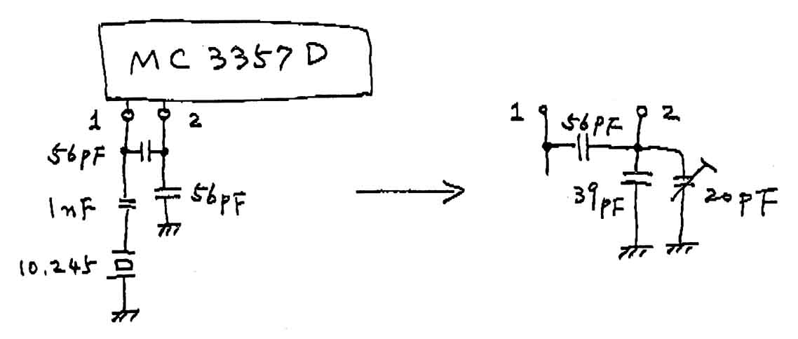
TOP
EARLY AR5000 - squelch tail characteristics
The length of squelch tail obtained on the AR5000 is microprocessor controlled and can be altered by PC via the RS232 port when using the Hyperterminal program.The following commands are required to do this:-
|
AR5BA4 (CARRIAGE RETURN) CMA518 (CARRIAGE RETURN) 00 (CARRIAGE RETURN) |
The AR5000 will now have to be re-set by pushing the button behind the brake lever.
This will give a minimum squelch tail but the 00 values can be substituted by any value up to 99 to give a longer squelch tail.
A low-level oscillation may be present between 400MHz and 1GHz which may cause a long squelch tail or simply be heard imposed on top of the wanted receive signal. S meter readings may alter in sympathy with the oscillation.
This problem has been reported as possible on an early AR5000 but it has only been observed on one set (A version V3.0 set).
This can be improved by the addition of a small grounded shield fitted to screen Q10 (FSX52WF) on the RF board.
TOP
EARLY AR5000 - increased noise level / AGC
In early AR5000 units under certain circumstances, the S-meter can be seen to give a reading, an increase in background noise or a clicking sound can be heard under `no signal' conditions. This is noticeable when a strong signal has ended or the RF gain control has been increased.The problem appears to be due to an instability starting in the 10.7MHz section and its symptoms can be altered by changing AGC settings, modes, etc.
A cure for this problem is to add a 22ohm resistor in the IF chain in place of R352 (RF PCB).
No alteration in receiver performance is noticed.
TOP
EARLY AR5000 - spurii at 200kHz spacing
It has been found on some AR5000 that there are a number of low-level birdies generated between 300 MHz and 1GHz. To observe these birdies set the squelch control to threshold point, disconnect the external antenna, set to NFM and rotate the main tuning knob. The squelch will open every 200kHz approx.The cure is to add a 10.7 MHz trap between the output from the DDS system and ground.
To carry out the modification remove the top cover and locate the PLL board - nearest the front panel with the metal screening cans and TCXO. Remove the six screws holding this board and hinge it over the front panel, removing necessary connectors - protect the top of the front panel with a soft cloth. The trap consists of a 4.7uH choke in series with a 47pF capacitor. It is connected between pin 3 of the NCO1 and ground. NCO1 is located at the left-hand side of the PLL board - pin 3 is counted from the rear of the underneath of the board and is the pin whose track obviously goes to the double balanced mixer DBM1. A suitable ground connection is either pins 1 or 2 of the NCO1.
Reassembly is a reverse of the above.
TOP
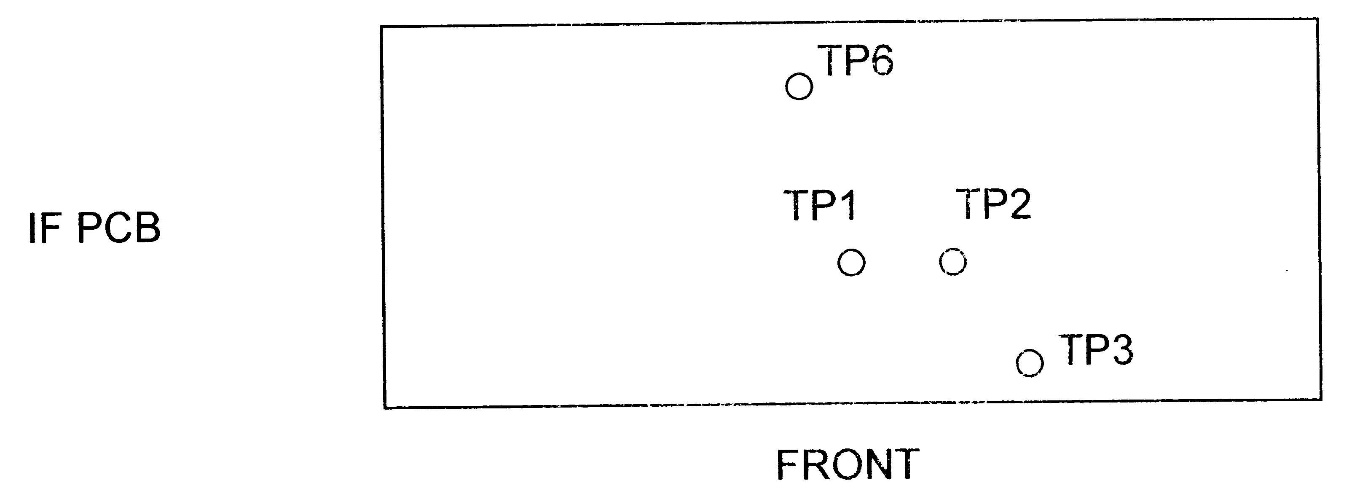
AR5000 455kHz I.F. output modification
The AR5000 can be easily modified to give a 455KHz I.F. output. This can be done by removing the top cover only. Various points are provided on the IF board which are intended as test points but can easily be soldered to in order to obtain an I.F. output. The I.F. board is the rearmost board once the top cover is removed.Various levels can be obtained depending at which point the signal is taken from. All points are clearly labelled on the board and there is no need to remove the board.
TP6 This point will give a low-level output (or can be used as an I.F. input) up to about 4mV (p/p). It is unfiltered by the 455 I.F. filtering at this stage and will be relying on the 10.7MHz filtering for its bandwidth. This test point is fed by a 0.1uf cap and 18Kohm res.
TP1 This is fed directly from the first stage of amplification after the 455KHz I.F. filtering has taken place. Levels will be up to approximately 3mV (p/p).
TP2 This is probably the most useful point to take the IF from. It is taken from the unused output of the secondary winding of I.F. transformer, T11, after the second stage of amplification after filtering. Output levels will be up to 10mV (p/p).
TP3 This gives a large level output after the third stage of amplification of the filtered signal. It is fed via a 0.1uf cap and 10Kohm res. Output levels will reach up to 1.5v (p/p).
All of the above points have no D.C. voltages present and TP1 & 2 are coupled indirectly to ground. These points can be brought out to the rear panel by connection of miniature R.F. coax. Termination can be made at an additional suitable socket of one of the ones already fitted can be utilized if it is not being used (possibly 10.7MHz output of 10MHz ref' input BNC).
TOP
DS8000 voice inverter - available sub-carriers
The optional DS8000 analogue speech inverter works well with the AR5000 receiver, please refer to the operating manual for fitting instructions.However, only FOUR sub carrier (inversion points) are supported, then they are repeated over-and-over... these frequencies are:
| 3.7kHz |
| 3.5kHz |
| 3.3kHz |
| 3.1kHz |
These tones are primarily intended for the decoding of Japanese cordless phones but may be used for simple PMR systems such as PMR446 etc.
Note: on the AR5000A+3, the DS8000 fits underneath the AFC unit, look for the sub-PCB marked P-9808A, J10 is underneath it!
TOP
AR5000 relay switching frequencies
Operators have reported mechanical 'clicks' emanating from inside of the AR5000 when scanning, this is most noticeable when sited in a quiet environment such as night-time monitoring from home. The clicks are caused by internal relays, diodes have not been employed for critical RF signal paths in an attempt to reduce signal loss and minimize intermodulation products.In particular it has been reported that the 'clicks' are most noticeable when the AR5000 is tuned across the following frequency boundaries:
| 40MHz |
| 400MHz |
| 1000MHz (1GHz) |
| 1600MHz (1.6GHz) |
Similar noise is generated by the earlier AR3000A receiver but is consistent with other manufacturers models such as the ICOM IC-R8500.
TOP
AR5000 tuning encoder adjustment and replacement
A pdf file is available detailing the replacement of main tuning encoder of the AR5000. Usually replacement is only necessary if mechanical damage has been experienced.To download the file - click here
The main encoder used (ALPS) has a specification of; 'approaching 100 pulses per revolution'.
Tuning the encoder at about 1 rev' every 5 seconds produces the nearly ideal figure of 100 steps.
Reducing the time to 4 seconds produced 96 steps
3 s 81 steps
2 s 76 steps
1 s 40 steps
0.5 s 20 steps
In practice, this produces a noticeable increase in tuning speed with increase in rotation speed up to about 1 rev / second. After that the tuning speed remains the same regardless of how much faster the encoder is rotated. The overall result is a very smooth tuning action while retaining reliable slow speed tuning.
There is very little circuit involved between the encoder and the microprocessor, just a couple of resistors and some decoupling. It appears therefore that the tuning rate is controlled mainly by the microprocessor firmware.
The main encoder is not intended to operate like an old VFO control. It is more intended as a 'rotary switch' used for several other functions in addition to frequency tuning. Operation of some of these other functions would be more difficult and jumpier if the encoder response speed was very different.
It is a wide band monitor and will never compete with the tuning operation of a VFO controlled dedicated HF set where tuning speed is directly proportional to speed of rotation. This being one reason that the AR5000 has such a versatile and large variety of programmable tuning step sizes with a different step size possible on the sub encoder.
TOP
AR5000 VLF sensitivity measurements
All tests in USB mode, 3kHz filter, AMP on, 0db ATT 10dBS/N| Receive frequency | Sensitivity |
|---|---|
| 100k | -122 dBm (0.18uV) |
| 50k | -119 dBm (0.25uV) |
| 35k | -116 dBm (0.35uV) |
| 30k | -112 dBm (0.55uV) |
| 25k | -108 dBm (0.9uV) |
| 20k | -104 dBm (1.4uV) |
| 15k | -101 dBm (2.0uV) |
| 10k | -97 dBm (3.2uV) |
| 6k | -76 dBm (35uV) |
TOP
AS5000 switch - circuit diagram
An optional switch is available for the AR5000, the part number is AS5000. The switch plugs into the rear panel ANT1 N-connector providing three N-sockets and leaves the rear chassis ANT-2 SO239 socket still available. Switching can be accomplished automatically using a defined form of bandplan or manually from the ANT select menu. The circuit is shown here: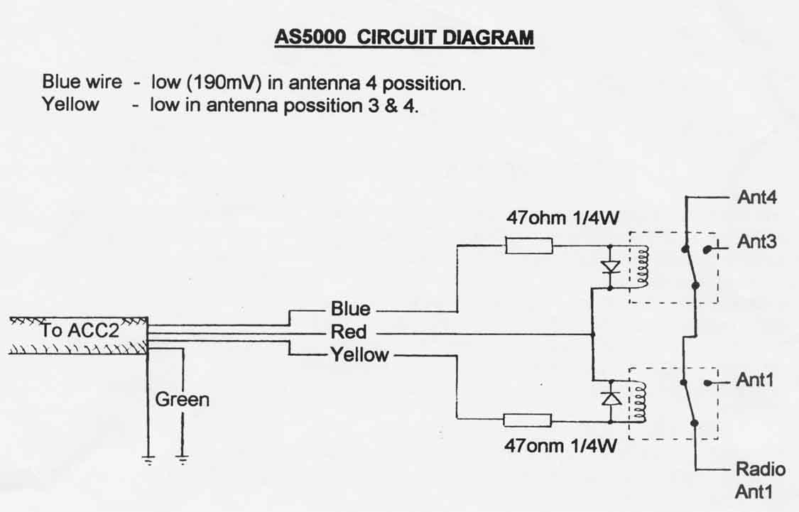
TOP
AR5000 Main encoder shaft bearing
The AR5000 uses a rotary encoder for its main tuning control. The shaft is supported through the front panel by a bronze type bearing mounted in a pressed steel case.The bearing is mounted to the front chassis by two screws.
The bearing doesn't use any lubrication and should normally operate without problem.
We have had a couple of reports of slightly stiff tuning and requests about how to lubricate this.
If the tuning is slightly stiff, chances are that it is the bearing mounted slightly off center.
To rectify this, remove the main encoder tuning knob by first sliding off the outer rubber sleeve and then loosen the small hex grub screw (only one is fitted even though there may be holes for two).
Loosen the two bearing screws now revealed.
Re-tighten these with the bearing re-positioned centrally.
If you decide to lubricate the bearing, use a light oil that will not stiffen with time.
Note that the bearing is free to rotate in its casing and the shaft free to rotate in the bearing itself, so lubrication can be added to both of these areas. Only add a small amount of oil as the main dial brake operation may be compromised if too much is added.
At worst, on well used older sets, it may be worth removing the bearing completely. Clean both the bearing and the shaft with a solvent before lubricating and re-fitting. Take care not to let any solvent enter the actual encoder as this will lead to very rapid wear.
Re-fit the encoder and test your work.
TOP
AR5000 RS232 commands for UP / DOWN tuning
The following commands can be used via Windows Hyper-Terminal using the ALT key of the PC and the NUMERIC KEYPAD (NOT the number keys above the keyboard letters):| Up arrow | ALT+30 HOLD ALT and type 30 |
|---|---|
| Down arrow | ALT+31 HOLD ALT and type 31 |
The AR5000 RS232 protocol listing is supplied with the radio.
To clarify, Up/Down Increment n<CR> where n is a binary byte value as follows
| UP | 0x1e |
|---|---|
| DOWN | 0x1f |
This would suggest that the command is expressed as a SINGLE HEX VALUE followed by carriage return. Ensure that you have full 8-bit data setup and not limiting it to 7-bit ASCII... otherwise all other commands would be okay but the HEX
TOP
DTMF device
DTMF is provided as standard in the AR5000 receiver. The decoder is an LM73881M, it is located on the Audio Power Unit (P-9411P-1) and is part number IC12.TOP
Squelch range
The squelch range of the AR5000 is characterized below. If you need to reduce the sensitivity to weak signals, you can use the advanced features of LEVEL SQUELCH / ATTENUATOR etc. Normal hysteresis is present.Receive frequency is for this test is 145.000MHz, NFM with 15kHz filter:
- Squelch threshold occurs just after the 10 o'clock position and opens with about 0.1uV signal
- 12 o'clock opens with signals around 0.15uV
- 3 o'clock opens with signal levels of around 0.2uV
- Maximum clockwise setting opens with signal levels of around 0.22uV
So, the squelch range is less then 10dB, 7dB in the case of the unit under test on this occasion.
TOP
AR5000 use with Opto scout
The AR5000 has an RS232 socket on the rear panel (not TTL or CIV), so a suitable control level needs to be obtained.In the AR5000, connect the RD line on the `Remote 4' board to an unused pin on ACC2 socket (pin 4 is not used, pin 7 can be used if pin 4 is already taken up for another use, pin 8,9,10 & 11 are connected to ground).
The remote 4 board is the small board fastened to the rear panel directly behind the RS232 9 pin D socket, ACC2, ext speaker and ext mute sockets (it has a MAX232 chip on it).
The RD line can be taken directly from pin 9 of the MAX232 chip, from connector J1 pin 3 or the choke in between these points (all on the same board).
A lead can now be made up directly from the ACC2 socket to the Opto. One point to watch is that a small bodied 2.5mm jack plug should be used otherwise there may not be room for this and external power to be connected at the same time (using a right angle plug usually overcomes this problem).
TOP
Please note that the information is supplied “as is” without any support nor obligation. This model is no-longer accepted for repair and none of the parts are available anymore.
www.aorja.com